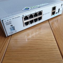
You have a Cisco FTD device that you manage via FDM, and you would like to setup port forwarding. In the example below I will forward TCP Port 80 (HTTP) traffic from the outside interface of my FTD Device (Firepower 1010) to an internal web server on 10.254.254.212
Solution (Step 1: Create an FTD NAT Policy)
Using a web browser connect to the FDM > Polices > NAT > Add.
Set the following options;
Title: Give the NAT rule a title e.g. Webserver-01
Create Rule for: Manual NAT
Status: Enable
Placement: Above a Specific Rule
Rule: InsideOutsideNATRule
Type: Static
Original Packet: Source Interface: inside
Original Packet: Source Address: Select ‘Create New Network’
In the Add new Network Object Window;
Name: Name of the server/object you are port forwarding to e.g. Webserver-01
Host: IP address of the server/object you are port forwarding to
OK
Back At the NAT Rule Window;
Source Address: Ensure it’s set to the object you just created
Original Packet: Source Port: HTTP (or whatever port you wish to forward)
Translated Packet: Destination Interface: outside
Translated PacketSource Address: Interface
Translated Packet: Source Port:HTTP (or whatever port you wish to forward)
OK.
Solution (Step 2: Create an FTD Access Control Policy Rule)
Policies > Access Control > Add.
Set the access rule as follows;
Title: Give the access rule a title e.g. Webserver-Access
Source Zone: outside_zone
Source Networks: any-ipv4
Source Ports: ANY
Destination Zone: inside_zone
DestinationNetworks: The Object you created (above)
Destination: Ports/Protocols: HTTP
OK
You can expand the rule, and see a diagram version if you wish.
Pending Changes > Deploy Now.
Wait! The changes probably haven’t deployed yet, you can check progress by clicking the pending changes button again.
Related Articles, References, Credits, or External Links
Note: This is for Cisco ASA 5500, 5500-x, and Cisco Firepower devices running ASA Code.
Note2: If your firewall is running a version older than 8.3 you will need to scroll down the page.
Port forwarding on Cisco firewalls can be a little difficult to get your head around, to better understand what is going on remember in the “World of Cisco” you need to remember two things…..
1. NAT Means translate MANY addresses to FEW Addresses
2. PAT Means translate MANY addresses to ONE Address.
Why is that important you ask? Well most networking types assume NAT is translating one address to many, BUT on a Cisco device this is PAT, and it uses (as the name implies) port numbers to track everything. e.g. the first connection outbound might be seen on the firewall as 123.123.123.123:1026 and the second connection outbound might be seen as 123.123.123.123:2049 so when the traffic comes back the firewall knows where to send it.
Fair enough but what has that got to do with Port Forwarding? Well you can use the exact same system to lock a port to an IP address – so if only one port can go to one IP address then that’s going to give you port forwarding 🙂
To make matters more confusing (sorry) you configure PAT in the NAT settings, for this very reason it confuses the hell out of a lot of people, and the GUI is not intuitive for configuring port forwarding, (the ADSM is better than the old PIX PDM) but most people, (me included,) prefer to use command line to do port forwarding.
Note: This option uses ASDM Version 7.9(2) If yours is older see below;
Connect to the ASDM, Configuration > Firewall > NAT Rules > Right Click ‘Network Object Nat Rules’ > Add ‘Network Object’ Nat Rule.
Name = “Give the internal server/host a sensible name” > Type = Host > IP Address = The internal / private IP address > Type = Static > Translated address = Outside > Advanced > Source Interface = Inside > Destination Interface = Outside > Protocol = TCP > Real port = http > Mapped Port = http > Ok > OK > Apply.
Note: This assumes your Outside interface is called outside, Inside interface is called inside and you want to port TCP port 80 (http).
Interface = Outside > Action = Permit > Source = Any > Destination {Browse} > Locate the object you created earlier > Add to Destination > OK.
Service {Browse} > Select the Port you require (i.e. http) > OK.
OK > Apply > When you have tested it works, save the changes.
Using Older ASDM (PIX V7 and ASA5500) 1 Port to 1 IP Address
1. As above you will need to know the port and the IP to forward it to, Launch the ASDM, Select Configuration > Security Policy > Then either Rule Add, or right click the incoming rules and select “Add Access Rule.”
2. Interface = Outside > Direction = Incoming > Action = Permit > Source = Any > Destination, Type = Interface IP, Interface = Outside > Protocol = TCP > Destination Port Source = smtp (for example) > OK > Apply.
3. Back at the main screen select Configuration > NAT > Add, or Right Click an Existing mapping and click “Add Static NAT Rule.”
4. Real Address Interface = Inside > IP Address = 10.254.254.1 > Netmask = 255.255.255.255 > Static Translation Interface = outside > IP Address = (Interface IP) > Tick “Enable Port Translation (PAT) > Protocol = TCP > Original Port = smtp > Translated Port = smtp (for example) > OK > Apply.
5. File > “Save Running Configuration to Flash.”
Option 2 Use the Command Line to Port Forward (Post Version 8.3)
Note: Port forwarding changed on PIX/ASA devices running OS 8.3 and above, in regards to port forwarding. There is no longer a global command, for a full run-down of the changes click here.
If you issue a global command after version 8.3 you will see this error,
ERROR: This syntax of nat command has been deprecated.
Please refer to “help nat” command for more details.
1. First things first, you will need to know what port you want to forward, and where you want to forward it, for this example We will assume I’ve got a server at 10.254.254.5 and it’s a mail server so I want to Forward all TCP Port 80 traffic (HTTP) to it. Connect to the Firewall via Console/Telnet or SSH.
[box]
Warning Notice
User Access Verification#
Password:********
Type help or '?' for a list of available commands.
Petes-ASA>
[/box]
2. Enter enable mode, and enter the enable mode password.
[box]
Petes-ASA> enable
Password:********
Petes-ASA#
[/box]
3. Now we need to go to configuration mode.
[box]
Petes-ASA# configure terminal
Petes-ASA(config)#
[/box]
4. Create an object for the web server that the traffic is going to be forwarded to.
6. Now you need to allow the http traffic in. Before you can add an ACL you need to see if you already have one. We are applying an ACL to the outside interface for traffic going in (I call this inbound for obvious reasons). To see if you already have an ACL applied, issue the following command;
[box]
Petes-ASA# show run access-group
access-group inbound in interface outside
access-group outbound in interface inside
[/box]
Note: In the example above we have an ACL called inbound that we MUST use. (If you added a new one, all the access list entries for the old one get ‘Un-applied’). If yours has a different name (e.g. outside_access_in then use that instead of the ACL name I’m using here). If you DONT have an access-group entry for inbound traffic then we will do that at the end!
[box]
Petes-ASA(config)# access-list inbound permit tcp any object Internal_Web_Server eq http
[/box]
7. Then: Only carry out the following command if you DO NOT HAVE an ACL applied for incoming traffic.
[box]
Petes-ASA(config)# access-group inbound in interface outside
Petes-ASA(config)#
[/box]
8. Don’t forget to save your hard work. (write memory).
object network Internal_Web_Server
host 10.254.254.5
nat (inside,outside) static interface service tcp http http
access-list inbound permit tcp any object Internal_Web_Server eq http
access-group inbound in interface outside
[/box]
Use the Command Line to Port Forward (pre version 8.3) 1 Port to 1 IP Address
1. First things first, you will need to know what port you want to forward, and where you want to forward it, for this example we will assume I’ve got a server at 10.254.254.1 and it’s a mail server so I want to forward all TCP Port 25 traffic to it. Connect to the Firewall via Console/Telnet or SSH.
[box]
Warning Notice
User Access Verification
Password:*******
Type help or '?' for a list of available commands.
Petes-ASA>
[/box]
2. Enter enable mode, and enter the enable mode password.
[box]
Petes-ASA> enable
Password: ********
Petes-ASA#
[/box]
3. Now we need to go to configuration mode.
[box]
Petes-ASA# configure terminal
Petes-ASA(config)#
[/box]
4. Now you need to allow the http traffic in. Before you can add an ACL you need to see if you already have one. We are applying an ACL to the outside interface for traffic going in (I call this inbound for obvious reasons). To see if you already have an ACL applied, issue the following command;
[box]
Petes-ASA#show run access-group
access-group inbound in interface outside
access-group outbound in interface inside
[/box]
Note: In the example above we have an ACL called inbound that we MUST use. (If you added a new one, all the access list entries for the old one get ‘Un-applied’). If yours has a different name (e.g. outside_access_in then use that instead of the ACL name I’m using here). If you DON’T have an access-group entry for inbound traffic then we will do that at the end!
5. Then: Only carry out the following command if you DO NOT HAVE an ACL applied for incoming traffic.
[box]
Petes-ASA(config)# access-group inbound in interface outside
Petes-ASA(config)#
[/box]
6. Lastly the command that actually does the port forwarding, (static command). And allow the traffic in.
Option 3 Use the PIX Device Manager (PIX Version 6 Only)1 Port to 1 IP Address
1. As above you will need to know the port and the IP to forward it to, Launch the PIX Device manager, Select Configuration > Access Rules > Then either click “Rule”s > Add or Right click an incoming rule and select > “Insert Before” or “Insert After”.
2. Under the “Action” select “Permit”, Under Source Host/Network Select “Outside”, and all the zeros, Under Destination Host/Network Select “Inside” and all the zeros then set the “Destination Port” to smtp > OK > Apply.
3, Now select the “Translation Rules” tab, Rules Add or Right click a rule and select “Insert before” or “Insert After”.
4. In this example I’ve set it to forward all TCP Port 25 traffic to 10.254.254.10 (NOTE: I’ve blurred out the public IP Address you will need to add this also) > OK > Apply.
5. Finally save your work > File > “Save Running Configuration to Flash.” > Exit.
Related Articles, References, Credits, or External Links
OK to be honest, before I went to work for my current employer I didn’t even know Symantec made hardware firewall’s, and at the time of writing they no longer make “Low End” firewall’s and corporate support for them has all but ended. With this in mind there are a load of them currently being replaced with newer firewall’s and they are either getting thrown in cupboards “In case of emergency” ending up on eBay, or worst of all going in the skip.
So why would you want one then?
Because in true Petenetlive fashion you can pick them up for nothing, or for a few pounds on eBay, and they make an excellent firewall for your Home PC, Home network or Small business.
Fair enough but what’s the difference between the two?
Basically both firewall’s can function as a hardware firewall and do site to site VPNS, the FW200 however can have 2 WAN connections and the 200R supports client to gateway VPN connections using the Symantec Client VPN software. Both appliances have a built in switch, on the FW100 its a four port and on the FW200 its an eight port.
FW100 (Top) and FW200 (Bottom)
To see what the Warning Lights and Symbols mean CLICK HERE
Right I’ve bought one now what the hell do I do with it?
That depends on what you want it for, there are a number of things a firewall can do, you can simply run through the basic setup and it will protect you PC/Network, or you might want to set up a permanent connection from home to your office (Site to Site VPN). Or you might want to access your PC’s at home or in the office from anywhere in the world with an internet connection (Client to Gateway VPN – FW200R only) You may have a server at home or an Xbox and want to Port forward particular traffic to a particular PC/Server or games console.
You can do as much or as little as you like with it, Ill outline the basic things you may want to do below
If you have got an appliance of ebay or been given it by work then chances are you wont know its settings and the password to get in an manage it so before you do anything you need to reset the appliance back to its factory settings. Read the ENTIRE procedure before you do anything!
3. Password is set to {Blank} – That’s NO Password.
4. Outside Interface(s) set to obtain their IP address dynamically.
5. Appliance turns on its internal DHCP server and leases addresses from its switch ports.
6. All traffic will be allowed out
7. No traffic will be allowed in (unless its a reply to traffic instigated inside).
On the back of the alliance you will see a row of “dip” switches, you can turn on (down) and off (up) With the unit powered off make use a pen, or paperclip and have a couple of practice flicks on switch 1
Procedure
1. Power off the appliance
2. Drop dip swich1 to ON
3 Power on the appliance and watch the backup/active LED Light come on (This one )
4. As soon as the LED goes out flip dip switch 1 up(off) , down (on), and up(off) again – note you only get 12 seconds!
5. If you have carried out the procedure correctly then the Error LED will come on (This one )and then alternate with the LAN/WAN Status LED (This one ).
6. The Appliance will reboot let it do so then remove the power, wait a few seconds, and power it up again.
Connect to the Firewall for Administration
Assuming you have just reset the firewall then its internal IP address will be 192.168.0.1, then simply connect your PC or Laptop to the firewall using a standard ethernet cable to any of the ports labelled LAN
Your PC should be set to get an IP address dynamically – Or Manually set an IP address in the 192.168.0.2 to 254 range. Then open a web browser and go to http://192.168.0.1
Standard front Page here on a FW100
And here on a FW200 (note the second WAN settings)
Note: You can manage these firewall’s from outside for example from work, BUT you need to enter the IP range that you will be administering from, to do this Select the “Expert Level” section and enter the range (note if you only have 1 IP add it in the start and End IP address section. you then access the device from http://public_IP_address:8088
Remember this is a firewall always set a password for access, select the “Config Password” Section then type and re-type a password. Then Press Save
Now to access the firewall the username is admin and the password you set above.
Upgrade the Firmware
You might wonder why bother – well I’ve used these firewall’s in anger on corporate networks, and I’ve seen strange problems with VPN’s and other bugs that have been fixed by simply upgrading the firmware – remember these are old firewall’s so the last version of firmware released for them (Called 18F was released Nov 2005) The FW100 firmware is here vpn100_build18f and the FW200 firmware is here vpn200r_build18f. You will also need the nxtftpw.exe program you can download that here nxtftpw.
To check your Firewall’s Firmware version connect to the firewall as above and Select the Status section > Then the Device section. here you will see the firmware revision. This one says V1 Rel 8D so its version 18D we are going to upgrade it to 18F.
To Prepare the firewall for firmware updating, Power it off and drop dip switches 1 and 2 on the back. Then Power the firewall back on again.
On your PC launch nxtftpw.exe and enter the following information, under Server IP enter the IP address of the firewall. An in Local file navigate to the firmware file on your PC.
Warning: there are two versions of the firmware file, one looks like vpn100_18F_app.bin the other looks like vpn100_18Fall.bin use app.bin the all.bin will erase the configuration as well!
Click PUT.
It might take a while and say its re tying a few times, be patient, when its finished it will say SUCCESS at the bottom.
Wait a couple of minutes, when the lights on the appliance all return to normal shut it down. Lift all the dip switches again and power back up.
Log back into the firewall and Check the firmware revision on the Status Tab > Device Section to make sure the version is correct, it should say V1 Rel 8F.
Basic Setup
For a simple home user you will want to set an external IP with a default gateway, some DNS settings. Then set your internal IP.
Main Setup Tab
If your ISP supplies your IP address via DHCP you don’t need to do anything that’s the default – note if you have a router that needs PPPoE settings these can be set up on this tab as well. Click Save when finished
Static IP & DNS Tab
Or if you have a static IP address enter it here with the subnet mask and the default gateway supplied by your ISP. Also note you can statically assign DNS servers here too, then your internal clients can point directly to the Symantec Firewall for their DNS settings. Click Save when finished
LAN IP & DHCP
Set your inside interface here – Note you can also set the firewall up as a DHCP server for your network as well. Click Save when finished.
Port Forwarding
Not all port forwarding is used for servers and complicated communications, simply downloading torrent software or playing online games may require you to forward a port to one of your clients. For this example I’ll port forward TCP Port 3389 (that’s RDP for the non tech’s do you can connect to your PC and server from outside – note doing this in the real world has security implications and is done at your own risk).
Custom Virtual Servers Tab
You need to give the protocol you are forwarding a name, like RDP, Tick Enable, Enter the IP address you want to forward it to, Then enter the port number into ALL FOUR box’s. When done click “Add.”
This is what you want to be seeing 🙂
You will see the rule added at the bottom of the page – Note: As I said this is quite a security hole, so you can tick and un tick enable, then tick update to turn on and off as required.
Site to Site VPN
A site to site VPN connects one network to another securely, across an insecure network (in almost every case the insecure network is the public internet) So you can connect two offices together, or connect your home PC(s) to the office network. You need a device at both ends that can terminate a VPN. At our end we have the Symantec the other can be your corporate firewall or a VPN server.
To form a VPN you need both ends to agree a “Policy” as there are different methods of forming a VPN, the device at the other end must use the SAME settings as you do.
OK what do I need to know?
Encryption method: We will use 3DES Hashing Method: We will use SHA1 Diffie Hellman Group: we will use Group 2 IP address of the other Firewall: We will use 123.123.123.123 Network address of the Other network (the far one you are connecting to): We will use 10.1.0.0 Subnet Mask of the Other network (the far one you are connecting to): We will use 255.255.0.0 A Pre shared Key: we will use qwertyuiop123
Note: This firewall uses a system called PFS. Tell the Firewall administrator at the other end of the tunnel to make sure that end has it enabled.
VPN Dynamic Key Tab
Give it a descriptive name > Tick Enable > PPPoE Session set to Session 1 > Select Main Mode > ESP3DESSHA1 > SA Lifetime to 475 > Data Volume Limit to 2100000 > PFS enable
Gateway Address set to the IP of the other firewall > ID Type to IP Address > Pre Shared Key to qwertyuiop123 > NETBIOS Broadcast to Disable > Global Tunnel to Disable > Remote subnet to the network at the other end of the tunnel > Remote Mask to the mask at the other end of the tunnel. > Click Add
Hopefully you will see this.
You will then see the tunnel appear at the bottom of the screen.
And the connection will change colour and say “Connected” when the tunnel comes up.
Client to Gateway VPN (200R Only)
In a client to gateway scenario, you install the client software on a laptop or remote PC, you then use that software to connect to your network behind the firewall. With this method you can securely connect many clients to one firewall.
OK What Do I need to Know?
A username: We will use Jane A shared secret: We will use 1234567890qwertyuiop
VPN Dynamic Key Tab
This sets the levels and method of encryption used by your remote clients, Type the name clients into the name box > Enable > Session 1 > Aggressive mode > ESP3DESSHA1 > 475 Mins > 2100000 > PFS enable > Gateway Address to 0.0.0.0 > ID Type to Distinguished Name. Click Add
VPN Client Identity Tab
Enter the username > Tick Enable > Type in the shared secret > Tick Add > The user will be displayed at the bottom.
Obviously this procedure is carried out on the remote PC/Laptop
Once you have the software installed (Note you need to le a local system administrator to this bit – or the software wont let you in) Fire up the software and give yourself a username and password (This can be anything – its just to log into the software NOT bring up the VPN). You will be asked to confirm the password.
This is the main screen, you can save many tunnels to many firewalls, but we are just dealing with one, click new.
On the gateway tab, in IP address enter the IP of the outside of the firewall > Make sure download VPN policy is NOT checked > enter your shared secret 1234567890qwertyuiop (as set up on the firewall > Your client phase 1 ID is the name on the firewall – in the example above that’s “jane”
Click the Advanced Tab > Under Gateway Phase 1 ID re-enter the IP address of the outside of the firewall.
Click the Tunnels Tab > Click New.
Tunnel name HAS TO match the policy you created on the firewall (in out case “clients”) Then enter the network address and subnet mask of the network BEHIND the firewall you are connecting to. > OK > OK.
Back at the main screen click the Policies Tab > Set “Port Control Type” to “Wide Open”.
Click the Gateways Tab > Log Off > Close and restart the client software > Select the tunnel and click connect > In the progress log when you see a message stating “security gateway connected”.
Related Articles, References, Credits, or External Links
This procedure was carried out on a Draytek Vigor 2800 Router, for this I needed to forward RDP (That’s on TCP Port 3389).
Warning: If you need to forward any of the following ports 23 (Telnet), 80 (HTTP) , 443 HTTPS/SSL), 21 (FTP), or 22 (SSH). The Draytek has these reserved for remote management. You will need to change the port number (system Maintenance > Management > Management Port Setup).
Solution
1. Log into the routers web console (default will be a blank username and password, or admin and admin, or admin and blank password).
2. Give the service a name (Like RDP) > Enter the protocol type TCP or UDP > Enter the internal IP that you want to forward the port to > Tick active > Click OK.
Note: Depending on setup you may see this instead (if that’s the case select the correct public IP)
3. That should be all you need to do, unless the firewall is turned on, if that’s the case expand NAT > Open Ports.
4. Again enter a name in the comment box > The local IP of the machine > and the port details > OK.
Related Articles, References, Credits, or External Links
If you have a server or host that you want to be publicly addressable and only have one public IP address then port forwarding is what you require.
Solution
Assumptions
1. You have a public IP on the outside of your Router.
2. You are performing NAT from your internal range of IP address to your External IP address.
To Make Sure
1. Run the following command:
[box]PetesRouter#show run | include ip nat inside[/box]
You should see a line like,
[box]ip nat inside source list 101 interface Dialer0 overload[/box]
2. That means NAT all traffic that access-list 101 applies to, to Dialer0 (this is an ADSL router and that’s it’s outside interface). To see what traffic is in access-list 101 is issue the following command:
[box]PetesRouter#show run | include access-list 101[/box]
You should see a line like,
[box]access-list 101 permit ip 10.10.0.0 0.0.255.255 any[/box]
3. This means permit (apply this ACL) to all traffic from 10.10.0.0/16 to anywhere. So its set to NAT all traffic from the inside network to the outside network.
4. Finally to see what IP is on your Dialer0 issue the following command:
[box]PetesRouter#show ip interface brief | exclude unassigned[/box]
You should see something like this
Now we know all traffic from 10.10.0.0/24 (All inside traffic) will be NAT translated to 123.123.123.123
Set up Port Forwarding
In this case Ill port forward TCP Port 443 (HTTPS) and TCP Port 25 (SMTP) to an internal Server (10.10.0.1).
1. First set up the static NAT translations.
[box]
PetesRouter#ip nat inside source static tcp 10.10.0.1 443 123.123.123.123 443 extendable
PetesRouter#ip nat inside source static tcp 10.10.0.1 25 123.123.123.123 extendableOR If you are running with a Public DHCP address
PetesRouter#ip nat inside source static tcp 10.10.0.1 443 interface Dialer0 443
PetesRouter#ip nat inside source static tcp 10.10.0.1 25 interface Dialer0 25
[/box]
2. Second stop that traffic being NATTED with everything else.
[box]
PetesRouter#access-list 101 deny tcp host 10.10.0.1 eq 443 any
PetesRouter#access-list 101 deny tcp host 10.10.0.1 eq 25 any
[/box]
3. Save the changes with “copy run start”, then press enter to access the default name of startup-config:
[box]
PetesRouter#copy run start
Destination filename [startup-config]?
Building configuration...
[OK]
PetesRouter#
[/box]
Setup port forwarding and restrict it to an IP or network
For things like HTTPS and SMTP you might want them accessible from anywhere but you might want to lock down access for something like RDP, (TCP port 3389) if that’s the case then you need to do the following.
1. Create a new ACL that allows traffic from you but denies it from everyone else (remember to put an allow a permit at the end).
[box]
PetesRouter#access-list 199 permit tcp host 234.234.234.234 host 123.123.123.123 eq 3389
PetesRouter#access-list 199 deny tcp any host 123.123.123.123 eq 3389
PetesRouter#access-list 199 permit ip any any
[/box]
Note: To allow a network substitute the first line for,
4. Finally apply the ACL you created inbound on the Dialer0 interface.
[box]
PetesRouter#configure terminal
Enter configuration commands, one per line. End with CNTL/Z.
PetesRouter(config)#interface Dialer0
PetesRouter(config-if)#ip access-group 199 in
PetesRouter(config-if)#exit
PetesRouter#
[/box]
5. Save the changes with “copy run start”, then press enter to access the default name of startup-config:
[box]
PetesRouter#copy run start
Destination filename [startup-config]?
Building configuration...
[OK]
PetesRouter#
[/box]
Related Articles, References, Credits, or External Links
This method provides failover to a redundant ISP link should your primary network connection go down. IT IS NOT going to load balance the traffic across both interfaces. In this example I’ve also got a VPN to a remote site and some port forwarding to contend with as well.
Where we are at the start.
Where we want to be
Solution
Before you go any further the ASA that will have the backup ISP line, needs a Security Plus Licence or it’s not going to work.
PetesASA>
PetesASA> en
Password: *******
PetesASA#
PetesASA# configure terminal
PetesASA(config)# interface Ethernet0/3
PetesASA(config-if)# nameif backup
PetesASA(config-if)# security-level 0
PetesASA(config-if)# ip address 234.234.234.234 255.255.255.248
PetesASA(config-if)# no shutdown
PetesASA(config-if)# exit
PetesASA(config)#
[/box]
2. In a ‘Failed Over’ state your traffic needs to then be NATTED to the backup interface, then setup a new route for the outside interface, and finally one for the backup interface. Note: The new primary route will be “Tracked” based on an SLA we will configure in a minute.
[box]
Configure NAT for a firewall running an OS NEWER than 8.3
PetesASA(config)# object network obj_any-01
PetesASA(config-network-object)# subnet 0.0.0.0 0.0.0.0
PetesASA(config-network-object)# nat (inside,backup) dynamic interfaceConfigure NAT for a firewall running an OS OLDER than 8.3
PetesASA(config)# global (backup) 1 interface
INFO: backup interface address added to PAT pool
Configure the Routes
PetesASA(config)# route outside 0.0.0.0 0.0.0.0 123.123.123.124 1 track 1
PetesASA(config)# route backup 0.0.0.0 0.0.0.0 234.234.234.235 2
[/box]
3. Now we are going to setup a new SLA that maintains connectivity to an IP address (In this case 4.2.2.2 via ICMP, then we are going to tie that SLA to “track 1”, )which you will remember is what keeps the default route on the Primary ISP), if that route fails, it swaps to the backup route.
[box]
PetesASA(config)# sla monitor 100
PetesASA(config-sla-monitor)# type echo protocol ipIcmpEcho 4.2.2.2 interface outside
PetesASA(config-sla-monitor-echo)# num-packets 3
PetesASA(config-sla-monitor-echo)# frequency 10
PetesASA(config-sla-monitor-echo)# sla monitor schedule 100 life forever start-time now
PetesASA(config)# track 1 rtr 100 reachability
PetesASA(config)#
[/box]
4. Any port forwarding getting done on the outside interface needs a mirror entry for the backup interface. and also will need matching ACL’s
5. Lets test it, issue a “show route” command, then disconnect your primary ISP then issue another “show route” command and it should have failed over like so;
[box]
PetesASA(config)# show route
Codes: C - connected, S - static, I - IGRP, R - RIP, M - mobile, B - BGP
D - EIGRP, EX - EIGRP external, O - OSPF, IA - OSPF inter area
N1 - OSPF NSSA external type 1, N2 - OSPF NSSA external type 2
E1 - OSPF external type 1, E2 - OSPF external type 2, E - EGP
i - IS-IS, L1 - IS-IS level-1, L2 - IS-IS level-2, ia - IS-IS inter area
* - candidate default, U - per-user static route, o - ODR
P - periodic downloaded static route
Gateway of last resort is 123.123.123.124 to network 0.0.0.0
C 234.234.234.0 255.255.255.248 is directly connected, backup
C 123.123.123.0 255.255.255.240 is directly connected, outside
C 10.0.0.0 255.255.255.0 is directly connected, inside
S* 0.0.0.0 0.0.0.0 [1/0] via 123.123.123.124, outside
PetesASA(config)#
Now Disconnect the Primary line
PetesASA(config)# show route
Codes: C - connected, S - static, I - IGRP, R - RIP, M - mobile, B - BGP
D - EIGRP, EX - EIGRP external, O - OSPF, IA - OSPF inter area
N1 - OSPF NSSA external type 1, N2 - OSPF NSSA external type 2
E1 - OSPF external type 1, E2 - OSPF external type 2, E - EGP
i - IS-IS, L1 - IS-IS level-1, L2 - IS-IS level-2, ia - IS-IS inter area
* - candidate default, U - per-user static route, o - ODR
P - periodic downloaded static route
Gateway of last resort is 234.234.234.235 to network 0.0.0.0
C 234.234.234.0 255.255.255.248 is directly connected, backup
C 10.0.0.0 255.255.255.0 is directly connected, inside
S* 0.0.0.0 0.0.0.0 [254/0] via 234.234.234.235, backup
PetesASA(config)#
[/box]
6. To enable this firewall to accept the existing VPN on its backup interface, you need to add the backup interface to that cryptomap (issue a show run crypto if your unsure). Then you need to enable ISAKMP on the backup Interface.
PetesASA(config)# wr mem
Building configuration...
Cryptochecksum: 91d190ba 2a3eb9c4 244d8c88 0da54e36
10220 bytes copied in 3.740 secs (3406 bytes/sec)
[OK]
PetesASA(config)#
[/box]
Change the ASA at the Remote VPN Site
1. Connect to the firewall at the remote site, find the cryptomap that points to the main site (show run crypto). find the one that pointing to the IP at the main site, then add the new IP address as an alternate peer address.
[box]
RemoteSite(config)# crypto map outside_map 2 set peer 123.123.123.123 234.234.234.234
[/box]
2. Then create a tunnel group for the new backup address with the same shared secret as tunnel group to the primary IP.
RemoteSite(config-tunnel-ipsec)#write mem
Building configuration...
Cryptochecksum: 7a455ca7 3b637757 cd40aa82 7f3a22d8
7842 bytes copied in 1.530 secs (7842 bytes/sec)
[OK]
RemoteSite(config-tunnel-ipsec)#
[/box]
To test the VPN fails over, at the remote site issue a “show cry isa” command, then get someone at the primary site to disconnect the primary ISP, wait a few seconds and then re-issue a “show cry isa” command and it should have flipped over.
[box]
Failover-FWall# show cry isa
Active SA: 1
Rekey SA: 0 (A tunnel will report 1 Active and 1 Rekey SA during rekey)
Total IKE SA: 1
1 IKE Peer: 123.123.123.123
Type : L2L Role : responder
Rekey : no State : MM_ACTIVE
Now Disconnect the Primary line at the Main site
Failover-FWall# show cry isa
Active SA: 1
Rekey SA: 0 (A tunnel will report 1 Active and 1 Rekey SA during rekey)
Total IKE SA: 1
1 IKE Peer: 234.234.234.234
Type : L2L Role : responder
Rekey : no State : MM_ACTIVE
[/box]
Related Articles, References, Credits, or External Links
I see this question get asked a lot on forums, most people never touch the firewall, ‘if it’s working leave it alone’. And that’s great until you move offices, or get a newer faster (or cheaper) Internet connection.
What if you have lots of public IP addresses? What if you have VPN’s (or AnyConnect clients). What’s the best way to do this with a minimum of downtime?
Note: If you get your all your outside IP details via DHCP, and no one speaks you you from outside (i.e. The ISP always reserves and issues the same IP details to you because you have a mail server or have VPN connections etc). Then you can probably simply plug into the new Router/Modem/Socket and reboot the ASA.
Solution
Time spent on reconnaissance is seldom wasted.
OK lets not run to the comms rack with a laptop and get stuck into the problem, get all your ducks in a row first.
1. Your Current Internet Connection: I know you’re going to turn this off, but if there’s a problem and everything ‘goes to hell in a hand cart’, you might need to connect back to this one in a hurry, (best not to look like a clown because you deleted all those settings and don’t know what they are). As a bare minimum have the following;
IP Address(s) allocated to you from the ISP. (Including the subnet mask and IP of their router if applicable).
Username and Passwords for your Internet Connection (if applicable i.e. for ADSL, PPPoE etc).
The details, of any public DNS records that point to you i.e. The MX records for your email, or URLs for any web services you host etc. If you have a web portal for managing this make sure you can log in. Or if your ISP handles this, get the information on how you can change your host records to point to the new IP address, (i.e. a fax on company headed notepaper, or a call to your account manager etc).
Then ring the old ISP make sure you can log a technical call without having to give them a password, (that everyone’s forgotten), or the only person who they will talk to left the company five years ago. (Get the feeling I’ve done this a lot!)
2. Your New Internet Connection: See everything you did above? get all the same information for the new ISP.
3. Backup: You are only ever as good as your last backup, make sure the ASA is backed up before you start, and backup to TFTP, or via the ASDMNOT by copy pasting the config into Notepad (this tends to hide shared secrets etc).
4. Test The New Internet Connection: I’ve had many a call from a colleague, that they can’t get an ASA working through a new Internet connection. And when I tell then to turn off the ASA and plug their Laptop into the Router/Modem/Socket guess what? Yes, the connection that the salesmen at the ISP said was live, really isn’t!
Warning: Sometimes you find that if you have used the public IP your ISP gave you on your laptop, that when you plug in the ASA it won’t work, (this happens because the router ‘caches’ the MAC address of the Laptop, and get confused when the ASA uses the same IP). So if possible use a different IP for testing, (if you have more than one IP). Or turn the ISP equipment off for a while after testing.
5. Who talks to you? What speaks to the ASA from outside? Do you have a web server, email server, FTP server, public facing service. Do have other offices that connect to you via VPN? Do you have remote workers that connect via VPN/AnyConnect?
5a. What Other Public IP’s Do You Use? You may have covered this in point 5 but now I’m talking about the public IP addresses that are in use but NOT assigned to the outside interface. Typically these are used in what we call static NAT.
If you have other sites with VPNs to you, they will need changing to point to the new public IP address.
Now you’ve read all the above, you have a better appreciation of what you might break, and how much downtime to expect. The outside interface of the ASA is exactly the same as any network connection it needs an IP address, a subnet mask, and a default route (same as default gateway for you Windows types).
Again never assume the outside interface is called ‘outside’, I’ve seen all sorts of naming outside, Outside, Public, WAN etc. You already know the public IP so let’s see what the interface name that’s using it is;
Petes-ASA> enable
Password: ********
Petes-ASA# show ip
System IP Addresses:
Interface Name IP address Subnet mask Method
GigabitEthernet0 outside 91.91.91.1 255.255.255.248 CONFIG
GigabitEthernet1 inside 192.168.1.1 255.255.255.0 CONFIG
Current IP Addresses:
Interface Name IP address Subnet mask Method
GigabitEthernet0 outside 91.91.91.1 255.255.255.248 CONFIG
GigabitEthernet1 inside 192.168.1.1 255.255.255.0 CONFIG
Petes-ASA#
Or on an ASA 5505
Password: ********
Petes-ASA# show ip
System IP Addresses:
Interface Name IP address Subnet mask Method
Vlan1 inside 192.168.1.1 255.255.255.0 CONFIG
Vlan2 outside 91.91.91.1 255.255.252.248 CONFIG
Current IP Addresses:
Interface Name IP address Subnet mask Method
Vlan1 inside 192.168.1.1 255.255.255.0 CONFIG
Vlan2 outside 91.91.91.1 255.255.252.248 CONFIG
Petes-ASA#
Notice: On smaller ASA's the IP address is allocated to a VLAN, on larger ones the IP
is allocated to a physical interface. Also the 'Method' says 'CONFIG', if it said DHCP
then you are getting these settings dynamically from your ISP.
Now we know out interface name and where the IP address and the subnet mask are. Now we need to locate the default route for the ‘outside’ interface, (or whatever yours is called).
ASA-1# show run route
route outside 0.0.0.0 0.0.0.0 91.91.91.2 1
ASA-1#
Or to get the same information from the routing table;
Petes-ASA# show route
Codes: C - connected, S - static, I - IGRP, R - RIP, M - mobile, B - BGP
D - EIGRP, EX - EIGRP external, O - OSPF, IA - OSPF inter area
N1 - OSPF NSSA external type 1, N2 - OSPF NSSA external type 2
E1 - OSPF external type 1, E2 - OSPF external type 2, E - EGP
i - IS-IS, L1 - IS-IS level-1, L2 - IS-IS level-2, ia - IS-IS inter area
* - candidate default, U - per-user static route, o - ODR
P - periodic downloaded static route
Gateway of last resort is 10.2.2.10 to network 0.0.0.0
C 91.91.91.0 255.255.255.248 is directly connected, outside
C 192.168.1.0 255.255.255.0 is directly connected, inside
S* 0.0.0.0 0.0.0.0 [1/0] via 91.91.91.2 outside
Petes-ASA#
Now you know the interface name, you know know its physical name, (GigabitEthernet0, Vlan 2, etc.) You have all the information you need to change the IP address, subnet mask and default route.
Petes-ASA> enable
Password: *********
Petes-ASA# Configure Terminal
Petes-ASA(config)# int gigabitEthernet 0
Petes-ASA(config-if)# ip address 60.60.60.1 255.255.255.240
Petes-ASA(config-if)# exit
You can only have one 'Default route', so you can't just add the new one, (or it will error)
so you need to remove that route, (by prefixing the command with a 'no'). Then add the new
default route in.
Note: If there's a number at the end of the route command, you can leave that off it's just
a routing metric number.
Petes-ASA(config)# no route outside 0.0.0.0 0.0.0.0 91.91.91.2
Petes-ASA(config)# route outside 0.0.0.0 0.0.0.0 60.60.60.2
In the ASDM you go to the same sections you did above, select the interface or route, click edit, then make the change. Note if you are going to use PPPoE read the following article.
Before we look at anything else we need to make sure the ASA has connectivity to the Internet, and THE ASA can ping a public ip address (Note: I said the ASA, not something on your network). I usually ping 8.8.8.8 (Google DNS server) because it always responds.
[box]
User Access Verification
Password: *******
Type help or '?' for a list of available commands.
Petes-ASA> enable
Password: ********
Petes-ASA# ping 8.8.8.8
Type escape sequence to abort.
Sending 5, 100-byte ICMP Echos to 8.8.8.8, timeout is 2 seconds:
!!!!!
Success rate is 100 percent (5/5), round-trip min/avg/max = 10/14/20 ms
Petes-ASA#
[/box]
If this fails, ensure you can ping your ISP router (default route IP) this should be pretty easy to troubleshoot with the assistance of the ISP.
Once the ASA can connect to the Internet make sure your internal clients can, remember if you are going to use ping to test connectivity though the firewall you need to have ICMP inspection setup see the following article;
If you are performing ‘port forwarding‘ from the outside interface, i.e. taking all SMTP (TCP Port 25) traffic and forwarding it to an internal host, then the firewall should require no further configuration as that should be done from the interface nameNOT the old public IP address.
You can quickly setup port forwarding if it’s stopped by reading the following article;
If you have public IP addresses statically mapped to public IP addresses from your old ISP range then these will need to be changed. here you can see Ive got a static NAT for an internal server;
To do the same in the ASDM, is a little more convoluted you need to check every NAT rule and see if you have one thats type is ‘static’ and has an IP address from your old ISP range, then you can change it accordingly.
Cisco ASA – Migrating VPN’s Post IP Address Change
Site to Site VPN
If you have site to site (IPSEC) VPN’s then these will have gone down when the public IP address changed. If the device at the other end is a Cisco ASA/PIX then follow the advice in the following article;
For remote workers using the older IPSECVPN client, you will need to send them a new PCF file to import into their VPN client with the new IP address in it, (unless they are pointing at your public DNS name, then you simply need to change the IP address that the DNS name points to). PCF files are explained in the following article;
As above if your AnyConnect clients connect directly to a public name like vpn.yourbusiness.com then just change that record to point to the new public IP address. Just be aware if you have set the AnyConnect profile to point to your old IP address, then your remote clients will automatically break themselves every-time they connect and download the profile, change it to the new IP address, or even better a public name/URL.
Dont Forget: Save any changes you have made to the firewall either with a ‘write mem‘ command, or File > Save running configuration to flash, if you’re in the ASDM.
I think I’ve got most stuff covered, if I’ve missed something that’s caused you problems let me know, and I will update this article accordingly (contact link below).
Related Articles, References, Credits, or External Links