
Cisco ASA Domain Authentication and Trust (Allowing)
ASA Domain Authentication KB ID 0000973 Problem I cringed this morning when I was asked about this, last time I had to get a client to authenticate to a domain through a firewall, it was ‘entertaining’. The problem is Windows loves to use RPC, which likes to use random ports, so to make it work you either had to open TCP ports 49152 and 65535 (Yes I’m Serious). Or you had to registry hack all your domain controllers...

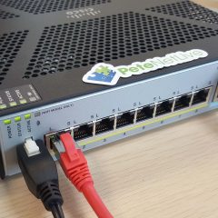
F5: Setup Basic Web Load Balancing
KB ID 0001698 Problem In past articles I’ve got my F5 BIG IP appliance up and running, and I’ve built some web servers to test load balancing. Now to actually connect things together and start testing things. Below is my lab setup, I will be deploying simple web load balancing (Static: Round Robin) between three web servers, each serving a simple HTTP web site. Test F5 to Web Server Connectivity For obvious reasons the F5...
Cisco AnyConnect – With Google Authenticator 2 Factor Authentication
KB ID 0001256 Problem This was asked as a question on Experts Exchange this week, and it got my interest. A quick search turned up a bunch of posts that said, yes this is possible, and you deploy it with FreeRADIUS and it works great. The problem was, a lot of the information is a little out of date, and some of it is ‘wrong enough’ to make the non-technical types give up. But I persevered, and got it to work. Disclaimer:...

Group Policy To Throttle Network Speed via QoS
KB ID 0001217 Problem Why would you want to do this? Well what if you want to test slow link group policy processing, or you are testing BranchCache? Using Group policy you can ‘throttle’ traffic to and from a particular IP address. Below I will pick a domain client on 192.168.110.120, and throttle all traffic between that client, and the domain controller to be 100kbps. Solution As I sad above I’m throttling...
VMware View 5 – Configure and Deploy Clients in ‘Kiosk Mode’
KB ID 0000610 Problem Kiosk mode is quite useful, if you have some machines that you want to put in a public area for visitors to use, or for machines that are used in displays etc. Or if you have some older PC’s that you just want to repurpose as internet terminals or ‘point of sale’ box’s. Essentially it’s a system that delivers a virtual VMware View desktop to a PC or Thin client without the need to...