Cisco Firepower 1010 (FTD) Initial Setup

KB ID 0001678


If you’re here you’ve either purchased a new Cisco Firepower device running FTD (FirePower Threat Defence) or have re-imaged your Firepower device from ASA to FTD code.

On its factory defaults, the unit will have the following settings.

  • Inside IP address (VLAN 1) 192.168.1.1 (on all interfaces from 2 to 8).
  • Outside IP Address set to DHCP in interface 1.
  • Management IP address 192.168.45.1 on the Management Interface.
  • DHCP Scopes on both the inside and management interfaces (192.168.1.x and 192.168.45.x respectively).

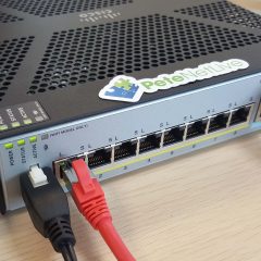
  1. Power Connector.
  2. 8 x Gigabit Ethernet ports: Normally GigabitEthernet 1/1 will be for the WAN, GigabitEthernet 1/2 though 1/8 will be for the LAN (with 1/7 and 1/8 being PoE).
  3. Management Port.
  4. Console Port (RJ45).
  5. Console Port (Mini USB).
  6. USB Port (useful for upgrades, and backups).
  7. Kensington Lock: Seriously? I’ve not seen one of these since about 2005, does anyone still use them?
  8. Reset Button: Depress for 3 seconds reverts the firewall to its factory settings, (and preserves the config apparently).
  9. Status Lights, (another reason not to put things on top of it!) Though you will notice there’s some on the back also. Note: When all lights are solid the firewall is operational, when the centre light is blinking, it’s still booting).

FirePower 1010 Setup

I will be deploying this as a stand alone FTD firewall, that will be managed locally on the device itself via FDM (Firepower Device Manager) and not via an FMC (Firepower Management Center) appliance.

Smart Licensing: If you’re not already familiar with Cisco Smart Licensing, I’ve covered it in more depth here. Set yourself up a free Smart License Account, and generate a token, copy it to the clipboard, (we will need it in a minute).

Connect to the firewall via a LAN port on https://192.168.1.1, or via the Management port on https://192.168.45.1 (unless you have ran though the FTD setup at command line, and have already changed the management IP).

Default usernames, (you will be asked to change them) are;

  • Username: admin
  • Password: Admin 123

Scroll down.

Here I’m accepting the default Outside/Public Interface settings of DHCP enabled, with IPv6 disabled, if yours has a static IP, or you want to user IPv6 then change the settings accordingly > Next.

I’ll accept the defaults here, be advised those NTP servers may take a little while to ‘go-green’ (you will see what I mean later) > Next.

I’m going to do this manually in a minute, so we can skip this > Next.

Note: The unit will have a default policy of let everything out (sourced from inside), and nothing in (sourced from outside) we will leave that as it is, as a decent start point.

Stanalone device > Configure Interfaces.

Note: Below I’m going to REMOVE the DHCP Scope, then change the ‘inside’ IP address (to avoid errors). Then later I will add the new DHCP scope back in again.

VLANs > Vlan1 > Edit. > DHCP section > Edit > Remove.

You can now set the inside IP address accordingly. (Don’t panic you wont lose connectivity yet!) > OK.

Now you need to Save/Commit the changes, and Deploy them. Now you will lose connectivity, if you have changed the inside IP address, so manually give yourself an IP address on the new network, and reconnect to the firewall.

Note: Update: Pleas ensure tha management is allowed in VLAN1 before proceeding (System Settings -> Management Access -> Data Interfaces.)

Cisco Firepower Setup DHCP

Create a new DHCP Scope: Should you require the firewall to be a DHCP server, log back in to the new internal IP address > System Settings > DHCP Server.

Create DHCP Server > Enable DHCP Server > Enter the new scope > OK.

Remember to commit the changes, and deploy them again!

Cisco Firepower FTD Licensing

Thankfully this is MUCH easier than doing the same thing while running ASA Code (on the same hardware!) > Smart Licence > View Configuration.

Register Device.

Paste in your token, (from above) > Set your location > Register Device. Go and have a coffee, it will look like it’s broken/not worked for a few minutes.

After a while you should see this;

There will be some outstanding changes to save and deploy also, now the unit is registered.

Back in the Cisco Smart Licence portal, it should look a bit like this;

Once fully complete and operational, all connected interfaces should have all the options ‘go-green’. For me the NTP servers took a while!

Note: Obviously the interfaces in orange are not in use!


Related Articles, References, Credits, or External Links

NA

DHCP Scope: Full of BAD_ADDRESS Entries

KB ID 0001651

Problem

I had a client machine struggling to get an DHCP address, and when I looked in DHCP the scope it was full of this;

BAD_ADDRESS This address Is Already in Use

Solution

A tour of Google and forums is full of posts by people with this problem, and other than, ‘Oh I looked in the logs and fixed it’ (with no mention of what log, or where this log was), or ‘Yeah I used Wireshark and located a problem client‘, then no follow up on what they did, or scanned for. So I pretty much had to slog through and work it out for myself. I’ll detail each step I took below, most of which didn’t help, or sent me in the wrong direction, but for you that may be a better solution.

And I will give you enough information to at least be helpful!

Firstly Common Sense Check: If this has just happened what have you changed? Have you added any Wireless Controllers, or Access Points? Have you deployed any new Switches or Firewalls. In my case, it was my test network so it could have been happening for months!

The most frequent cause of this error is simply because someone has setup another DHCP server on the network. That will be easy to diagnose, simply ‘Stop’ your DHCP Server;

Then on a DHCP client, issue an ifconfig /release and ifconfig /renew, If it gets an IP address, issue an ifconfig /all and look for the IP of the DHCP server it’s using, that’s your culprit. However as you can see, mine didn’t get an IP address so this wasn’t my problem.

The next most popular suggestion is to enable ‘Conflict Detection‘, though in most places the information on where to find this, is incorrect, (as it’s been copied and pasted around the forums without actually checking it!) See below, you locate it on the properties of the Protocol not the Server > Advanced Tab > You are supposed to set it between 1 and 6 so I went for 5, (but after deleting all the BAD_ADDRESS entries, they were all back after 30 minutes or so, so this didn’t work for me either).

Look in the logs: Well they were useless also, DHCP creates a new log every day in C:\Windows\System32\Dhcp called ‘DHCPSrvLog-DAY.log’ as you can see it was not helpful.

At this point I put my networking head on, and ‘thought outside the box’, If DHCP is detecting these as BAD ADDRESSES, then they must be in the arp cache on the DHCP server right? Well look at this;

[box]

arp -a

[/box]

Well that’s encouraging, at least now I’ve got a suspect MAC address, lookup up that MAC address online, and it comes back as VMWare (which sent me off in the wrong direction, it was not a VMware virtual machine in my vSphere in the end). Ive got a decent Cisco Switch so I thought I’d see which interface it was connected to, (but it wasn’t there).

[box]

show mac address-table

[/box]

At this point I was still thinking it was a VMware virtual machine, so I used PowerCLI (Thats PowerShell for VMware), to query for that MAC address, but that revealed nothing.

So, my last hope was Wireshark, I fired it up on the DHCP server, and set the filter to;

[box]

bootp.option.type == 53

[/box]

Then I deleted all the BAD_ADDRESS entries, left Wireshark ‘sniffing’, and went for lunch. I returned to this (see below). Now 192,168,100,107 was one of the BAD_ADDRESS entries, and I did not know what it was. The other entries on there for 192.168.100.3 are understandable, (that’s my DHCP server!) So now I had a Layer 3 address to hunt.

When I RDP connected to it, I got prompted for a password, so now I know it’s a Windows box! I hunted all through my VMware virtual machines, it was not there. Just as an afterthought I remembered I have a Hyper-V server, could that be running a virtual machine? BOOM! There is a SCVMM server, I was using for some Zerto testing a couple of months ago! Turned it off, problem solved!

Hope you find your culprit quicker than I did!

Related Articles, References, Credits, or External Links

NA

How Do I Find/Change My IP Address?

KB ID 0000208

What’s an IP address?

An IP address is the address used on a network to find your PC, Server, Laptop, or Printer etc. It’s the networking equivalent of your house number and post code (or Zip Code for visitors from over the pond).

Do you want your PUBLIC or PRIVATE IP address? As we started to run out of addresses, there were a number of solutions that we came up with, one you will see below (DHCP) the other is NAT (Network Address Translation) that lets many IPs on a network share one (or more) public IP addresses on the internet. If you want to know your PUBLIC address (your address in on the internet) then simply see below;

Your Public IP Address Is: [user_ip]

Where does my IP address come from?

You get an IP address by two methods,

1. Statically Assigned: Your address never changes and is allocated to you manually.

2. Dynamically Assigned: Your machine gets its IP address automatically via a system called DHCP.

What does an IP address look like?

Most IP addresses in use today are IP version 4 and consist of 4 numbers separated by three full stops (or once again, periods, for overseas visitors).

An IP address 192.168.1.100

Is that all my computer needs?

NO! You need FOUR pieces of information to access the internet and work properly;

1. The IP address itself (i.e. 192.168.1.100) this is unique to every machine on the network.

2. The Subnet Mask (i.e. 255.255.255.0) this tells the machine how big the network it is on, is.

3. The Default Gateway, this is another IP address on the network that you need to go through to get off the local network, i.e. to access the internet.

4. The DNS IP address, this is another IP address of a machine that can translate IP addresses into names (e.g. translate www.bbc.co.uk to 212.58.246.159).

What’s my IP address?

1. Windows Key + R > type ‘cmd’ {Enter}

2. A Command Window will open, click within the box and you can type in commands, the command to show your IP address is ipconfig, but this WONT show us the DNS settings as well, to do that the command is “ipconfig /all“.

Note: If you have many network connections you will get results for them all, you may need to scroll up and down to find the right one.>

IP Problems

Problem 1: My machine has got an IP address that is 169.254.x.y (where x and y can be any number from 1 to 254).

Answer: This machine is set to get its IP address automatically via DHCP but it cant speak to the DHCP server, because either the DHCP server is down or there is no connection between the DHCP server and you.

Problem 2: My IP address shows as 0.0.0.0

Answer: You have been given a static IP address and someone on the same network is using the same address, this causes an IP conflict, change one of the IP addresses.

Find out if your IP address is statically assigned of dynamically assigned

The more eagled eyed of you will see on the ipconfig /all results above that this machine is disabled for DHCP so its dynamically assigned however, on your Windows machine do the following.

1. Windows Key + R > Tyoe ‘ncpa.cpl’ {Enter}

2. Your network connections window should open and locate the connection you are connecting with (you might have many, be sure to select the right one, i.e. you might have one for dial up, one for wireless, one for a VPN to the office etc). Right click the connection and select properties.

3. On the window that appears you may have to scroll down the list, we are looking for its TCP/IP (on newer machines it will be called “Internet Protocol Version 4 (TCP/IPv4)”, Select it and click properties.

4. Now you can see if your addresses are set statically or dynamically.

How to change your IP address

To change your IP address you first need to know if you have a static IP address or a Dynamically assigned one. (That’s why this section is below the one above).

1. If you have a static IP address, simply change it on the screen shown (diagram above).

2. If you have a Dynamic IP address, you can either reboot the machine in question or Click Start > run > cmd {enter}

3. A Command Window will open, click within the box and you can type in commands, the command to release your IP address is ipconfig /release

Then to get a new address type in ipconfig /renew

Related Articles, References, Credits, or External Links

NA

Cisco ASA Site to Site IKEv2 VPN Static to Dynamic

KB ID 0001602

Problem

Site to Site VPNs are easy enough, define some interesting traffic, tie that to a crypto map, that decides where to send the traffic, create some phase 1 and phase 2 policies, wrap the whole lot up in a tunnel-group, and you’re done! But there needs to be a ‘peer address‘ in the crypto map, and if one end of the VPN is on DHCP that address is likely to change, so you cant supply that?

The solution is quite simple, Cisco had to address this years ago when they had remote IPSec VPN clients, you use a Dynamic Cryptomap, and because you can’t have a tunnel group either, you use the DefaultL2LGroup, (this gets used when a specific IP address is not defined).

Note: If you have many remote sites using DHCP why not consider configuring EZVPN instead?

Static IP ASA Config

Use the following, change the values in red, to suit your own requirements;

[box]

!
object network OBJ-MAIN-SITE-LAN
 subnet 192.168.1.0 255.255.255.0
!
object network OBJ-REMOTE-SITE-LAN
 subnet 192.168.2.0 255.255.255.0
!
access-list VPN-INTERESTING-TRAFFIC extended permit IP object OBJ-MAIN-SITE-LAN object OBJ-REMOTE-SITE-LAN
nat (inside,outside) source static OBJ-MAIN-SITE-LAN OBJ-MAIN-SITE-LAN destination static OBJ-REMOTE-SITE-LAN OBJ-REMOTE-SITE-LAN
!
crypto ipsec IKEv2 ipsec-proposal IPSEC-PROP-1
 protocol esp encryption aes-256
 protocol esp integrity sha-1
!
crypto dynamic-map DMAP-VPN 10 set IKEv2 ipsec-proposal IPSEC-PROP-1
crypto dynamic-map DMAP-VPN 10 set reverse-route
!
crypto map outside_map 999 ipsec-isakmp dynamic DMAP-VPN
crypto map outside_map interface outside
!
crypto IKEv2 policy 2
 encryption aes-256
 integrity sha512
 group 24
 prf sha512
 lifetime seconds 86400
!
crypto IKEv2 enable outside
!
group-policy GP-SITE-2-SITE internal
group-policy GP-SITE-2-SITE attributes
 vpn-idle-timeout none
 vpn-session-timeout none
 vpn-filter none
 vpn-tunnel-protocol IKEv2 
tunnel-group DefaultL2LGroup general-attributes
 default-group-policy GP-SITE-2-SITE
tunnel-group DefaultL2LGroup ipsec-attributes
 IKEv2 remote-authentication pre-shared-key Password123
 IKEv2 local-authentication pre-shared-key Password123
!

[/box]

Dynamic IP ASA Config

As above, change the values in red, to suit your own requirements, (this is essentially just a normal site to site IKEv2 config!)

[box]

!
object network OBJ-REMOTE-SITE-LAN
 subnet 192.168.2.0 255.255.255.0
!
object network OBJ-MAIN-SITE-LAN
 subnet 192.168.1.0 255.255.255.0
!
access-list VPN-INTERESTING-TRAFFIC extended permit IP object OBJ-REMOTE-SITE-LAN object OBJ-MAIN-SITE-LAN
nat (inside,outside) source static OBJ-REMOTE-SITE-LAN OBJ-REMOTE-SITE-LAN destination static OBJ-MAIN-SITE-LAN OBJ-MAIN-SITE-LAN
!
crypto ipsec IKEv2 ipsec-proposal IPSEC-PROP-1
 protocol esp encryption aes-256
 protocol esp integrity sha-1
!
crypto map outside_map 1 match address VPN-INTERESTING-TRAFFIC
crypto map outside_map 1 set pfs group5
crypto map outside_map 1 set peer 1.1.1.1
crypto map outside_map 1 set IKEv2 ipsec-proposal IPSEC-PROP-1
crypto map outside_map interface outside
!
crypto IKEv2 policy 2
 encryption aes-256
 integrity sha512
 group 24
 prf sha512
 lifetime seconds 86400
!
crypto IKEv2 enable outside
!
group-policy GroupPolicy_1.1.1.1 internal
group-policy GroupPolicy_1.1.1.1 attributes
 vpn-tunnel-protocol IKEv2
tunnel-group 1.1.1.1 type ipsec-l2l
tunnel-group 1.1.1.1 general-attributes
 default-group-policy GroupPolicy_1.1.1.1
tunnel-group 1.1.1.1 ipsec-attributes
 IKEv2 remote-authentication pre-shared-key Password123
 IKEv2 local-authentication pre-shared-key Password123
!

[/box]

Related Articles, References, Credits, or External Links

NA

Cisco IOS – DHCP Helper (DHCP Relay) – IP-Helper Setup

KB ID 0001168 

Problem

Cisco documentation calls this a ‘DHCP Relay’, and uses the command IP-Helper, and I usually call this DHCP Helper, just to confuse everyone. To be fair the term DHCP Relay is an industry standard, it’s not particular to Cisco (as you will see later when I Wireshark the traffic).

So If you are reading this you have a DHCP server and you want to use it to lease addresses to clients that are on a different network segment (layer 2, or layer3).

To do that you need an agent to be on the same network segment as the client listening for DHCP requests, when it receives one it talks to the DHCP server on the clients behalf and gets the correct address.

Solution

Example 1 Cisco Router

Here we need to lease two different DHCP scopes to two different network segments, R1 will act as the IP-Helper for both of those networks, R2 and R3 will get their IP addresses from the correct DHCP scope.

This works because each (client facing) interface on R1 has an IP-Helper address defined that points to the DHCP server.

So How Does It Know Which Scope To Lease From? This is because the Router supplies the IP address of a RELAY AGENT, which is just the IP address of the physical interface that intercepted the DHCP request. When it asks for an IP address from the DHCP server, the Server leases an address from the same range, (again I’ve tracked all this in Wireshark below).

IP-Helper Router Configuration

[box]

R1 Config

!
interface GigabitEthernet0/0
 description Uplink to DHCP Server
 ip address 10.2.2.254 255.255.255.0
 negotiation auto
!
interface GigabitEthernet2/0
 description Uplink to 192_168_2_0
 ip address 192.168.2.1 255.255.255.0
 ip helper-address 10.2.2.10
 negotiation auto
!
interface GigabitEthernet3/0
 description Uplink to 192_168_3_0
 ip address 192.168.3.1 255.255.255.0
 ip helper-address 10.2.2.10
 negotiation auto
!
ip route 0.0.0.0 0.0.0.0 10.2.2.10
!


R2 Config

!
interface GigabitEthernet2/0
 description Uplink to R1
 ip address dhcp
 negotiation auto
!
ip route 0.0.0.0 0.0.0.0 GigabitEthernet2/0
!

R3 Config

!
interface GigabitEthernet3/0
 description Uplink to R1
 ip address dhcp
 negotiation auto
!
ip route 0.0.0.0 0.0.0.0 GigabitEthernet3/0
!

[/box]

You can see this works because the DHCP server has matching scopes for both network segments. (Yes one of my test servers is 2003, you’re going to see some Windows XP in a minute!

Well that’s fine for routers, but what about machines? They send a DHCP Discover just like any other client. I’ve replaced one of the routers with an actual machine.

With its network card set to DHCP you will again get a lease from the correct scope, because the Router brokered it for us.

Back on the DHCP server you can see the lease to the windows XP machine entered in the current scope leases, It knows the name of the client because (as you will see below) the relay agent (Router) passed that information (along with the MAC address of the client) to the DHCP server.

Example 2 Cisco Switches

OK, I did the routers first because I find it easier to explain things at layer 3. Not that you can’t create sub interfaces on the router, add those sub interfaces to VLANs, and run DHCP relays from them. But in most cases you will be setting up DHCP helpers on switches. Here the principle is the same but you define the ip-helper on the VLAN, (unless it’s routed port then treat it the same as a router interface). Let’s modern things up a bit, and use a 2012 R2 DHCP server, and some Windows 8 clients.

I need to lease addresses from my second scope to clients in VLAN 200, (the other client and server are in the same VLAN, so that will just work. (Remember a VLAN is a broadcast domain, and DHCP is using broadcasts).

Here’s the two scopes setup on the 2012 server;

And my client, (DHCP Client in VLAN 200) gets the correct IP.

IP-Helper Switch Configuration (VLANS)

[box]

SW1 Config

interface FastEthernet1/0/1
 description Uplink to DHCP Server
 switchport access vlan 100
 switchport mode access
 spanning-tree pordtfast
!
interface FastEthernet1/0/4
 description Uplink 192_168_200_0
 switchport access vlan 200
 switchport mode access
 spanning-tree pordtfast
!
interface FastEthernet1/0/5
 description Uplink 192_168_100_0
 switchport access vlan 100
 switchport mode access
 spanning-tree portfast
!
interface Vlan200
 ip address 192.168.200.1 255.255.255.0
 ip helper-address 192.168.100.10
!

IF YOU HAVE MULTIPLE/FAILOVER IP-HELPERS OR SPLIT SCOPES YOU CAN ADD A SECOND 
ADDRESS LIKE SO;

!
interface Vlan200
 ip address 192.168.200.1 255.255.255.0
 ip helper-address 192.168.100.10
 ip helper-address 192.168.100.15
!

[/box]

Analysing (Packet-Sniffing) DHCP Relay Sequence with Wireshark

Other packet sniffers are available, but I’ve got a soft spot for Wireshark. To filter DHCP traffic you can use the following ‘filter’.

bootp.option.type == 53

DHCP works by using four messages, (which I remember using the acronym DORA: Discover, Offer, Request, Acknowledge). If you sniff the traffic on the DHCP server, you can watch this process being brokered by your DHCP Relay Agent.

Discover

Offer

Request

Acknowledge

And just to prove it’s not all ‘smoke and mirrors’, here’s the client with the leased address, showing a matching MAC address, and hostname.

Related Articles, References, Credits, or External Links

NA

Cisco IOS – Setting Up DHCP Scopes

KB ID 0001112 

I usually only have to do this on very small sites, or occasionally on the test bench. Most of the time we will have a server sat doing DHCP. The procedure below was carried out on a router, but the procedure is the same for a catalyst switch.

By default DHCP is disabled, you have to turn it on, then create a ‘dhcp pool.’

[box]

Petes-Router(config)#service dhcp
Petes-Router(config)#ip dhcp pool DATA-VLAN-10

[/box]

Then set the range of addresses and scope options.

[box]

Petes-Router(dhcp-config)#network 172.16.1.0 255.255.255.0
Petes-Router(dhcp-config)#default-router 172.16.1.1
Petes-Router(dhcp-config)#dns-server 8.8.8.8 8.8.4.4
Petes-Router(dhcp-config)#domain-name petenetlive.com
Petes-Router(dhcp-config)#exit

[/box]

Don’t forget to EXCLUDE the ip address of the router/switch from the DHCP scope, and any other static IP’s you have.

[box]

Petes-Router(config)#ip dhcp excluded-address 172.16.1.1

[/box]

There’s nothing to stop you running multiple scopes either, below I add another scope for my voice VLAN, and exclude the router IP on that VLAN, and my PBX.

[box]

Petes-Router(config)#ip dhcp pool VOICE-VLAN-11
Petes-Router(dhcp-config)#network 172.16.2.0 255.255.255.0
Petes-Router(dhcp-config)#default-router 172.16.2.1
Petes-Router(dhcp-config)#dns-server 8.8.8.8 8.8.4.4
Petes-Router(dhcp-config)#exit
Petes-Router(config)#ip dhcp excluded-address 172.16.2.1
Petes-Router(config)#ip dhcp excluded-address 172.16.2.250

[/box]

Related Articles, References, Credits, or External Links

NA

vSphere ESX – Configure Buffalo Terastation 5000 as an iSCSI Target

KB ID 0000899 

Problem

This little NAS box is a cheap way of adding a large amount of storage. Below I’m going to configure it as an iSCSI target, then connect my ESX5 host to it.

I’m not setting up any CHAP authentication, but I’ll show you where it’s configured, if you want to deploy yours a little more securely.

Also it’s considered good practice to separate your storage network traffic, from your actual network traffic (either physically or via VLANs). Here I’m also NOT doing that.

Solution

Initial Configuration of the TS5000

If you connect either of the NAS box’s NICs to your network they will pick up an IP address via DHCP (You will see it in your DHCP leases).

1. Connect to the NAS with a web browser, the default password is ‘password’.

2. To change the default password: Enter Easy Admin mode > Reset Password > Follow the instructions.

3. Team / Trunk The NICs: You can have each NIC with its own IP address, but I prefer to aggregate them > Network > Port Trunking > Configure port trunking.

4. Select ‘Link 1’.

5. Select All > Assign.

6. It may take a few seconds.

Configure iSCSI

7. First enable iSCSI > Drives > iSCSI > Click the switch to enable.

8. Configure iSCSI

9. Create Volume.

10. Give the volume a name, description, and specify the volume size > OK.

Note: If you wanted to configure authentication select enabled, and set accordingly.

11. Enter the numbers as requested > OK.

12. This can take a couple of minutes also.

Configure ESX For iSCSI

13. Connect to either your ESX host or vCenter > Select a host > Configuration > Networking > Add Networking > Create a new vSwitch > Add a VMkernel port group (called iSCSI or something sensible) > Assign a free NIC, and give it an IP address on the same range as the NAS box.

14. Storage Adaptors > If you do not see any, select ‘Add’ and add in a software iSCSI Adapter.

15. Right click your iSCSI Adapter > Network configuration > Bind it to the port group you created in step 13.

16. Then on either the Dynamic or the Static discovery tab, enter the IP address of the NAS box.

17. Storage > Add Storage > Disk/LUN > Select the iSCSI storage > Follow the instructions.

18. Repeat the process on your remaining ESX hosts. (Note: You will only need to create the VMFS volume(s) for the first one).

Related Articles, References, Credits, or External Links

Cisco Small Business (SG500) Link Aggregation (LAG) With LACP

BT Business ADSL – Configure a 2Wire Router to Allocate a Static (Public) IP Address

KB ID 0000760 

Problem

I know BT are now shipping the BT Business Hub, to their business ADSL clients, but there’s still a few 2Wire routers out there in the wild. Essentially if you have a range of public IP addresses, this is how to allocate one of the public IP addresses to one of your devices. In my case its a Cisco ASA firewall that I need to have a public IP.

Solution

Firstly I’m going to assume the router is working and connected to the internet, if there’s a problem and you need to reset it you will need the following pieces of information.

1. The BT ADSL Username and password.

2. The public IP address range allocated to you by BT (and the IP allocated to the router).

Note: Plug your device into the router before you start, and set it to get its address via DHCP.

1. Connect to the web interface of the 2Wire router (normally http://192.168.1.254) > Settings > Broadband > Link Configuration > Scroll down the page.

2. Locate the ‘Add additional network’ section > Add in the IP address that BT have told you to allocate to the router, the subnet mask will be provided by BT also, but you can work it out with my subnet calculator if you don’t know > Save >Enter the router password if prompted.

Note: By default the password will be the Serial Number of the router, (on the white sticker). If you have forgotten you can reset it.

3. Select the LAN tab > NAT & Address Allocation > Locate your device > Set the firewall to disabled > Address Assignment = Public (Select WAN IP Mapping) > WAN IP Mapping = Public Fixed {The IP address you want to assign} > Save > Enter the password if prompted.

4. This relies on the router providing DHCP, which it will do by default, though you can check on the Private Network tab.

5. Finally either reboot the device you are assigning the IP address to, (or ‘reload’ if it’s a Cisco ASA).

Related Articles, References, Credits, or External Links

NA

Windows XP – Sysprep (for imaging)

KB ID 0000599 

Problem

A client who we recently did a WDS (Windows 7) install for, needed to image a couple of Windows XP machines, (They had some software that either would not run, or was not supported on Windows 7).

They asked me for some documentation on how to do this, it’s been such a long time since I imaged any XP machine, so I took the opportunity to document it properly.

Solution

Before you begin, be aware you need to be building your reference machine with a Volume Licenced copy of Windows XP NOT an OEM or Retail copy (i.e. DONT build the machine with manufacturers rescue disks like Dell or HP). If you don’t do this you will need to activate every Windows machine that you deploy with Microsoft.

Make sure the version of sysprep you are using is at the same service pack level as the reference machine or bad things will happen.

Windows XP SP3 version of Deploy.cab

1. Build your reference machine, and configure it as you require.

2. Create a folder on the root of the C: Drive called ‘Sysprep”. Insert the Windows XP CD and locate the Deploy cabinet file. (This is ‘like’ a zip file and it’s in the supporttools folder).

3. Double click the support cab, then copy over the sysprep.exe file, the setupcl.exe file and the setupmgr.exe file to your c:sysprep folder.

4. You can now run sysprep.exe and skip to step 13. BUT if you require an answerfile (a script that will answer all the questions Windows will ask while it’s reinstalling post sysprep) then run the setupmgr.exe program, at the welcome screen click next.

5. Create New > Sysprep Setup > Windows XP Professional.

6. Fully Automate > Enter Name and Organisation > Set the Display Properties.

7. Set Time Zone > Enter the Volume Licence unlock code > If you are joining a domain, I suggest generating a random name then changing it later.

8. Set the Local Administrators password > Typical settings will enable DHCP > Supply any domain and domain credentials you need to join your domain.

9. Telephony (I just skip this) > Regional Settings > Languages.

10. Printers > Run Once commands > Additional Commands.

11. Enter a string that will go into the registry, and can be identified later > Finish > Accept the default save path > OK > At this point it looks like it’s crashed, you can manually close the setupmgr.

12. Now you can run sysprep.exe > OK > I select ‘mini-setup’ (If you don’t, it will run the welcome to windows session and play the annoying music you cant turn down!) > If you have installed applications and are going to image the machine click Reseal > OK.

Note: Factory will literally set the machine back to a ‘day one’ install of Windows XP.

The machine will then shut down and can be imaged.

Final Note: If you power it back on, it will rebuild itself and delete the c:sysprep directory. Which is fine unless you are doing some testing and realise you have to do the whole thing from scratch!

Related Articles, References, Credits, or External Links

Windows Deployment Services (Server 2003)
Deploying Windows XP

Windows Deployment Services (On Server 2008 R2)
Deploying Windows 7

Windows Server – DHCP Service Starts then Stops again

KB ID 0000617 

Problem

Saw this last week on an SBS 2011 Server. When attempting to get the DHCP service running it span up then stopped straight away.

Solution

A quick look in Event Viewer showed me what the problem was,

Event ID 1054

The DHCP/BINL service on this computer is shutting down. See the previous event log messages for reasons

Fair enough lets see the previous error on the same server;

Event ID 1053

The DHCP/BINL service has encountered another server on this network with IP Address, (IPv4 or IPv6 address), belonging to the domain

In this example the offending IP (192.168.87.254) Was a Cisco PIX 501 firewall that was running a DHCP server. Thankfully My main job that day was to replace the firewall so when I put in a new ASA I didn’t have the DHCPD service running.

If you see this elsewhere you will need to locate the offending IP and disable DHCP on it.


Related Articles, References, Credits, or External Links

NA