Cisco FPR – Re-image from FTD to ASA Code

KB ID 0001766

Problem

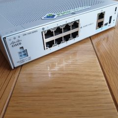
Note: This procedure is to re-image a Cisco Firepower device from FTD to ASA code, (in this example a Cisco FPR 1010). 

Why would you want to do this? Well to be frank FTD is bobbins, so if you have a device running FTD code you might want to ‘convert’ it to ASA code. If you tried to do this with an older firewall (ASA 5500-X) then you needed to go to Cisco TAC and try and get them to give you an activation code for the ASA. But if you are using an FPR device then YOU DON’T NEED TO DO THAT.

You might also want to do this because, (at time of writing) buying a Cisco FPR device running ASA code, the lead times in the UK are eye wateringly long (200-300 days!) But you can buy a chassis running FTD code and then convert that to ASA code with the following procedure.

Solution

Connect to your FPR device with a console cable, and log on as admin (the default password is Admin123, unless you have changed it of course!) Download the latest version of ASA code for your device from Cisco, in my case (at time of writing) that’s cisco-asa-fp1k.9.14.3.15.SPA. Copy that onto a USB drive (WARNING: The drive needs to be formatted with FAT32, the firewall will not recognise or mount the drive unless it is!) Finally insert the USB drive into the firewall, and issue the following commands.

[box]

FTD-1# scope firmware
FTD-1 /firmware # download image usbA:/cisco-asa-fp1k.9.14.3.15.SPA
Please use the command 'show download-task' or 'show download-task detail' to check download progress.
FTD-1 /firmware # show download-task

Download task:
    File Name Protocol Server          Port       Userid          State
    --------- -------- --------------- ---------- --------------- -----
    cisco-asa-fp1k.9.14.3.15.SPA
              Usb A                             0                 Downloading

% Download-task cisco-asa-fp1k.9.14.3.15.SPA : completed successfully.

[/box]

Note: If it says, ‘failed. Download failure – USB drive is not mounted‘ the drive is probably formatted incorrectly. If it says ‘Download-task failed. Failed signature validation‘, then the image is probably corrupt, try again, or use a different version.

Verify the file has downloaded correctly.

[box]

show download-task

Download task:
    File Name Protocol Server          Port       Userid          State
    --------- -------- --------------- ---------- --------------- -----
    cisco-asa-fp1k.9.14.3.15.SPA
              Usb A                             0                 Downloaded

[/box]

Then make sure the package is listed with a show package command.

[box]

FTD-1 /firmware # show package
Name                                          Package-Vers
--------------------------------------------- ------------
cisco-asa-fp1k.9.13.1.2.SPA                   9.13.1.2
cisco-asa-fp1k.9.14.3.15.SPA                  9.14.3.15
cisco-ftd-fp1k.6.6.0-90.SPA                   6.6.0-90

[/box]

Note: You can see (above) there’s an ASA code version from a previous install and it shows the current running FTD code also. To re-image the firewall execute the following commands. (Note: you enter the VERSION NOT THE FILENAME!)

[box]

FTD-1 /firmware # scope auto-install
FTD-1 /firmware/auto-install # install security-pack version 9.14.3.15

The system is currently installed with security software package 6.6.0-90, which has:
   - The platform version: 2.8.1.105
   - The CSP (ftd) version: 6.6.0.90
If you proceed with the upgrade 9.14.3.15, it will do the following:
   - upgrade to the new platform version 2.8.1.172
During the upgrade, the system will be reboot

Do you want to proceed ? (yes/no):yes {Enter}

This operation upgrades firmware and software on Security Platform Components
Here is the checklist of things that are recommended before starting Auto-Install
(1) Review current critical/major faults
(2) Initiate a configuration backup

Do you want to proceed? (yes/no):yes {Enter}

Triggered the install of software package version 9.14.3.15
Install started. This will take several minutes.
For monitoring the upgrade progress, please enter 'show' or 'show detail' command.
FTD-1 /firmware/auto-install #

[/box]

Now go and have a coffee, it will take 20 minutes, and a few reboots before it’s finished. When completed you should see a login prompt, login with admin/Admin123 and reset the password. 

[box]

firepower-1010 login: admin
Password: Admin123
Successful login attempts for user 'admin' : 1
Last failed login: Sun Nov 21 16:55:16 UCT 2021 on ttyS0
There was 1 failed login attempt since the last successful login.
Hello admin. You must change your password.
Enter new password: password123
Confirm new password: password123
Your password was updated successfully.

[/box]

Then connect to the ASA CLI with the connect asa command. Go to enable mode, and set the enable password. Finally, save the config.

[box]

firepower-1010# connect asa
firepower-1010# Verifying signature for cisco-asa.9.14.3.15 ...
Verifying signature for cisco-asa.9.14.3.15 ... success
ciscoasa>
ciscoasa> enable
The enable password is not set.  Please set it now.
Enter  Password: password123
Repeat Password: password123
Note: Save your configuration so that the password can be used for FXOS failsafe access and persists across reboots
("write memory" or "copy running-config startup-config").
ciscoasa# write memory
Building configuration...
Cryptochecksum: a607255a a64f2898 97bb6b40 9a8ff25c

[/box]

You will now be running ASA code with the factory settings (Inside 192.168.1.1/24, Management 192.168.45.1/24 (with DHCP enabled), Outside set to get IP dynamically, and all traffic allowed out).

Remember if you’re a ‘light weight’ and cant use command line, then you will need to install and configure the ASDM 🙂 

Related Articles, References, Credits, or External Links

Reimage Cisco 1010 ASA to FTD

Convert ASA 5500-X To FirePOWER Threat Defence

Convert MBR Partitioned Drives to GPT

KB ID 0001407

Problem

I got asked if I’d ever had to do this today, I vaguely remember having this problem in the past, but I can’t remember how I solved it. You set the ‘Partition Table Type‘ on a  disk in Windows, when the drive is first initialised, like so;

And the default is MBR, so that usually gets ticked, the problem is MBR only supports disks up to 2TB in size. Now if it’s just a new disk, with no partitions on it, you can simply change it;

But if it’s got a partition on it, (and probably some live data) you cant!

Previously, (before Windows 10, and Server 2016,) The Microsoft solution was to delete the partitions and create a new one, which can be a little time consuming, especially if you have live data on it! So can you convert it to GPT Live with no data loss? 

Solution

Yes! As usual, make sure you have a decent backup first, and if you are using a virtual environment, you can snapshot the virtual machine before hand, (I tested this in the lab, by taking a snapshot, converting a drive from MBR to GPT, then reverting to the snapshot, and it flipped back to MBR with no loss of data). 

You need to know what disk number Windows has assigned to the drive, in disk management right click the drive, and select properties.

Windows 10 and Windows Server 2016

Using this method will require (after you have finished) you machine. is set to UEFI boot, otherwise it will work fine until you try and reboot, then the machine won’t boot! So if you are doing this on a Virtual Machine in Hyper-V MAKE SURE it’s a generations 2 VM!

You will find MBR2GPT.exe in C:\Windows\System32, if it’s not there do a full round of Windows updates! Simply open an Administrative command window and run the following commands;

[box]

cd c:\windows\system32
mbr2gpt /convert /disk:1 /allowfullOS

[/box]

Take note of the warning the machine should now be set to UEFI boot mode, so if its a VMware VM, then change this value;

For OLDER Vesions of Windows

Download and extract gptgen-1.1 then run the following command;

[box]gptgen.exe -w \\.\\physicaldrive1[/box]

Note: Where ‘1‘ is the disk number you took note of above.

Note: If you see “Block read failed, check permissions!” Then you might want to use MBR2GPT {above} instead.

That’s it done! In ‘disk management’ you will need to ‘Rescan Disks’ to see the change.

In the unlikely event that something exploded, you can ‘roll-back‘ to your snapshot.

Related Articles, References, Credits, or External Links

NA

Migrate a VM from vCenter to Azure

KB ID 0001510

Problem

Last time we looked at migrating from vCenter to Hyper-V, now we will use the MVMC (Microsoft Virtual Machine Converter) to take a VMware (vCenter) virtual machine and convert/upload it to Microsoft Azure.

Note: MVMC is not ‘officially’ supported and this procedure requires you to create some ‘legacy’ (for legacy in Azure read ‘classic’) ways of doing things. So this might not be the tool for you. But if you want to go down this route, this is what you need to do.

The best approach is to use Azure Site Recovery (ASR)

A better option might be to use Veeam?

Solution

To connect the MVMC to Azure you need a ‘Management Certificate’ This can be a self generated (self signed) certificate. To create it on your MVMC machine execute the following commands;

[box]

Import-Module PKI
 
New-SelfSignedCertificate -DnsName "MVMC" -CertStoreLocation "Cert:\CurrentUser\My" 
 
Export-Certificate -Cert (Get-ChildItem Cert:\CurrentUser\My\ -DnsName MVMC) -FilePath $env:TEMP\MVMC.cer
Import-Certificate -FilePath $env:TEMP\MVMC.cer -CertStoreLocation Cert:\CurrentUser\Root

[/box]

Take a note of the Thumbprint. You will need this certificate thumbprint, and your Subscription ID. Once you have uploaded the certificate you’ve just created, to connect with MVMC. So now you need to connect to you Azure subscription.

All Services > Subscriptions.

Take a note of your subscription ID, then click the subscription.

Management Certificates > Upload > Location ether certificate in your temp directory, and upload it.

You need to create a ‘Classic’ Storage account > All Services > Storage Account (Classic) > Create Storage Account (Classic) > Choose classic deployment model (They hid that well!)

In case you are unfamiliar with Azure, you need a Resource group, in which the place this storage group, if you don’t already have one you can simply click ‘Create new’. Give your storage account a name > set the other values as shown. (Note: Not all locations support classic storage accounts) > Review and Create > Create.

It may take a few minutes.

Convert VMware VM and Upload to Azure

Launch MCVM > Set Virtual Machine Conversion > Next > Migrate to Microsoft Azure > Next.

Enter the Subscription ID and Thumbprint you made a note of earlier > Next.

Select your Storage Account > Next.

Note: If there is no option to select, you either didn’t create ‘classic’ storage, or you didn’t apply the ‘cup of coffee rule’. Go have a brew then try again.

Provide your vCenter Details > Next.

Select your VM to convert/upload > Next.

My VM is not a domain member so I’m supplying the local administrator credentials > I want to power the source VM off when conversion is done, the converted VM will simply be a new virtual disk in Azure so that will be off also > Next.

Warning: At this point the VM being converted needs to have its windows firewall off, and be able to be resolved in DNS (or when you click next it will error!)

Supply a folder with sufficient capacity, (twice the site of the source VM) in which to perform the migration > Next.

Check the details > Finish.

Note: If it fails with a descriptor error see the following article;

Conversion Error ‘Unsupported Disk Database Entry’

The conversion and upload should progress like so;

Back in Azure > All Resources > Select your storage account > Storage Explorer > Blob Containers > Theres our virtual disk.

All Services > Disks (classic) > Select your disk > Create VM.

Name the VM > Select the Resource group you used above > Next.

Choose a VM size > Select.

Give the VM a domain name, (you will use this to access the VM via RDP) > Next.

Review the details > OK.

All Services > Virtual Machines > Select your VM > Connect > This should download a rdp file which you can use to connect to the converted VM.

Related Articles, References, Credits, or External Links

NA

Cisco ASA – Converting IKEv1 VPN Tunnels to IKEv2

KB ID 0001196 

Problem

We’ve had IKEv2 support on Cisco ASA for a while, (since  version 8.4). I tend to setup site to site VPN tunnels at command line, and on the rare occasions I’m using the ASDM I normally just ignore the IKEv2 settings. Like all techies I know a way that works, so I will keep doing it that way.

What’s the difference between IKEv1 and IKEv2?

IKE version 2 is a lot more efficient and has a smaller network overhead, this is because it uses less messages to establish secure peers. Back with IKEv1 we had main mode (9 messages), and aggressive mode (6 messages), but IKEv2 only has one mode and that has only 4 messages. Back with IKEv1 both ends of the tunnel needed to use the same method of authentication (usually a shared secret (PSK) or an RSA Signature (Digital certificate). But with IKEv2 each end of the tunnel can use a different authentication method. Nat Traversal is automatically taken care of, and DoS Attacks can be mitigated by built in anti-replay, and cookie support to defend against flood attacks.


Solution

Migrating your tunnels from IKEv1 to IKEv2 is probably the easiest job you’ve been given, (it can be done with one command). But doing something, and understanding whats happening are two different things.

I usually use AES-256 and SHA for site to site VPNs so a typical config I would deploy would look like this;

[box]

crypto ikev1 enable outside
crypto ikev1 policy 10
authentication pre-share
encryption aes-256
hash sha
group 2
lifetime 86400
!
object network OBJ-MainSite
subnet 10.0.0.0 255.255.255.0
object network OBJ-RemoteSite
subnet 10.0.3.0 255.255.255.0
!
access-list VPN-INTERESTING-TRAFFIC extended permit ip object OBJ-MainSite object OBJ-RemoteSite
nat (inside,outside) source static OBJ-MainSite OBJ-MainSite destination static OBJ-RemoteSite OBJ-RemoteSite no-proxy-arp route-lookup
!
tunnel-group 2.2.2.2 type ipsec-l2l
tunnel-group 2.2.2.2 ipsec-attributes
pre-shared-key 1234567
isakmp keepalive threshold 10 retry 2
!
crypto ipsec ikev1 transform-set VPN-TRANSFORM esp-aes-256 esp-sha-hmac
!
crypto map CRYPTO-MAP 1 match address VPN-INTERESTING-TRAFFIC
crypto map CRYPTO-MAP 1 set pfs group2
crypto map CRYPTO-MAP 1 set peer 2.2.2.2
crypto map CRYPTO-MAP 1 set ikev1 transform-set VPN-TRANSFORM
crypto map CRYPTO-MAP interface outside

[/box]

Assuming both sites are OK and the tunnel is up, if we look to see what’s happening with ISAKMP we see something like this.

[box]

Petes-ASA(config)# show crypto isakmp
IKEv1 SAs:

   Active SA: 1
    Rekey SA: 0 (A tunnel will report 1 Active and 1 Rekey SA during rekey)
Total IKE SA: 1

1   IKE Peer: 123.123.123.123
    Type    : L2L             Role    : responder
    Rekey   : no              State   : MM_ACTIVE

[/box]

You do the entire conversion with one command ‘migrate l2l’, or if these are client to site VPNS you can use ‘migrate remote-access’

[box]

Petes-ASA(config)# migrate ?

configure mode commands/options:
  l2l            Migrate IKEv1 lan-to-lan configuration to IKEv2
  overwrite      Overwrite existing IKEv2 configuration
  remote-access  Migrate IKEv1 remote-access configuration to IKEv2/SSL
  
Petes-ASA(config)# migrate l2l
Petes-ASA(config)#

[/box]

Now ensure you do the same at the other end, (or ensure the other vendor supports IKEv2). BE AWARE: By default if you configure IKEv1 and IKEv2 the ASA will fall back to IKEv1 if it cannot negotiate IKEv2. At this point we already have a tunnel established, so we need to ‘bounce’ the tunnel to get it to re-esablish.

[box]

PetesASA(config)# clear crypto isakmp
PetesASA(config)# show cry isa
There are no IKEv1 SAs
IKEv2 SAs:

Session-id:1, Status:UP-ACTIVE, IKE count:1, CHILD count:1

Tunnel-id                 Local                Remote     Status         Role
 87787277       123.123.123.123/500      2.2.2.2/500      READY    INITIATOR
      Encr: AES-CBC, keysize: 256, Hash: SHA96, DH Grp:2, Auth sign: PSK, Auth verify: PSK
      Life/Active Time: 86400/7 sec
Child sa: local selector  10.0.0.0/0 - 10.0.0.255/65535
          remote selector 10.0.3.0/0 - 10.0.3.255/65535
          ESP spi in/out: 0xa5034be1/0x6c5de26e

[/box]

We are now running over IKEv2, to see how that’s changed the config see the differences below, highlighted in blue.

[box]

!
crypto ikev2 policy 10
 encryption aes-256
 integrity sha
 group 2
 prf sha
 lifetime seconds 86400
crypto ikev2 enable outside
!
crypto ikev1 enable outside
crypto ikev1 policy 10
authentication pre-share
encryption aes-256
hash sha
group 2
lifetime 86400
!
object network OBJ-MainSite
subnet 10.0.0.0 255.255.255.0
object network OBJ-RemoteSite
subnet 10.0.3.0 255.255.255.0
!
access-list VPN-INTERESTING-TRAFFIC extended permit ip object OBJ-MainSite object OBJ-RemoteSite
nat (inside,outside) source static OBJ-MainSite OBJ-MainSite destination static OBJ-RemoteSite OBJ-RemoteSite no-proxy-arp route-lookup
!
tunnel-group 2.2.2.2 type ipsec-l2l
tunnel-group 2.2.2.2 ipsec-attributes
pre-shared-key 1234567
ikev2 remote-authentication pre-shared-key 1234567
ikev2 local-authentication pre-shared-key 1234567
isakmp keepalive threshold 10 retry 2
!
crypto ipsec ikev1 transform-set VPN-TRANSFORM esp-aes-256 esp-sha-hmac
!
crypto ipsec ikev2 ipsec-proposal VPN-TRANSFORM
 protocol esp encryption aes-256
 protocol esp integrity sha-1
crypto ipsec ikev2 ipsec-proposal ESP-3DES-SHA
 protocol esp encryption 3des
 protocol esp integrity sha-1
crypto ipsec ikev2 ipsec-proposal ESP-AES-128-MD5
 protocol esp encryption aes
 protocol esp integrity md5
crypto ipsec ikev2 ipsec-proposal ESP-AES-192-SHA
 protocol esp encryption aes-192
 protocol esp integrity sha-1
crypto ipsec ikev2 ipsec-proposal ESP-AES-128-SHA
 protocol esp encryption aes
 protocol esp integrity sha-1
crypto ipsec ikev2 ipsec-proposal ESP-AES-256-SHA
 protocol esp encryption aes-256
 protocol esp integrity sha-1
crypto ipsec ikev2 ipsec-proposal ESP-3DES-MD5
 protocol esp encryption 3des
 protocol esp integrity md5
crypto ipsec ikev2 ipsec-proposal ESP-AES-192-MD5
 protocol esp encryption aes-192
 protocol esp integrity md5
crypto ipsec ikev2 ipsec-proposal ESP-DES-MD5
 protocol esp encryption des
 protocol esp integrity md5
crypto ipsec ikev2 ipsec-proposal ESP-DES-SHA
 protocol esp encryption des
 protocol esp integrity sha-1
crypto ipsec ikev2 ipsec-proposal ESP-AES-256-MD5
 protocol esp encryption aes-256
 protocol esp integrity md5
!
crypto map CRYPTO-MAP 1 match address VPN-INTERESTING-TRAFFIC
crypto map CRYPTO-MAP 1 set pfs group2
crypto map CRYPTO-MAP 1 set peer 2.2.2.2
crypto map CRYPTO-MAP 1 set ikev1 transform-set VPN-TRANSFORM
crypto map CRYPTO-MAP interface outside
!
crypto map CRYPTO-MAP 1 set ikev2 ipsec-proposal VPN-TRANSFORM
!

[/box]


Related Articles, References, Credits, or External Links

Cisco ASA 5500 Site to Site VPN (From CLI)

VMware ESXi – Converting ‘Thick’ Provisioned Drives to ‘Thin’, and ‘Thin’ to ‘Thick’

KB ID 0000579 

Problem

Thin provisioning of hard drives is pretty cool stuff, full support for thin provisioning was brought in with vSphere version 4. Put simply a thin proviosioned drive is as big as it needs to be, and a thick provisioned drive is set to its maximum size when it’s created. The virtual machines that use these hard drives don’t know, and assume that their hard drive is a set size (even if it is thin proviosioned).

Thick provisioned drives should be used for machines/applications that will have intensive input/output (RAW mappings are also better for this). But what happens if you want to convert them? From Thin to Thick is very simple (see below), But from Thick to thin is a little more convoluted.

Note: You can change drive provisioning by running the Converter on the virtual machine, and change the disk provisioning as part of the conversion process (click here for details).

Solution

ESXi Converting Thick to Thin Provisioned Drives

1. Here you can see I’ve got a VM (Server 2008 R2) with a 40GB vmdk file (Hard Drive). You can also see it’s in a datastore called ‘RAID5’. Before you start make sure the VM using this disk is shut down.

2. Log into your ESX box via SSH, I’m logged in as ‘root’ if you are not don’t forget to ‘su’. To find out what the symbolic link is for the RAID5 datastore issue the following comand;

[box] ls -l /vmfs/volumes/ [/box]

From the output below we can see RAID5 is called “4f214fe5-c5ce77b0-a889-00110a59a5d6”.

3. Using the Symlink and the path (from the datastore browser, see step one) you can construct the command, use the following syntax;

[box] vmkfstools -i /vmfs/volumes/{volume-symbolic-link}/{folder}/{original-drive-name}.vmdk /vmfs/volumes/{volume-symbolic-link}/{folder}/{new-drive-name}.vmdk -d ‘thin’ -a lsilogic [/box]

If you didn’t turn off the machine (I did tell you in step one!) you will see the following;

4. Now we have a “New” thin provisioned drive cloned form the old one, go to the properties of your VM (Edit Settings). And remove the old drive.

5. Then add in your new “Thin” Drive.

6. It should look a little like this.

7. Now power up your VM and, once you are happy, don’t forget to DELETE the old thick provisioned drive.

ESXi Converting Thin to Thick Provisioned Drives

1. This is much simpler to do; browse the datastore in question and locate the vmdk file you want to convert. Right click it and select “Inflate”.

8. The drive will be converted.

9. You can also see its progress in the VI client’s “Recent Taks”.


Related Articles, References, Credits, or External Links

Virtual Center (VIM) Resizing Guest Hard Drive Sizes With VMware Converter

Re sizing Windows Volumes / Drives in VMware vSphere / ESX

Outlook Error – ‘One or more users cannot be added to the folder access list. Non-local users cannot be given rights on this server’

KB ID 0000560 

Problem

Outlook will show you this error if you attempt to grant rights to a “distribution group” on an object for example, a public folder, or for calendar permissions.

You would think that converting the “Universal Distribution Group” to a “Universal Security Group” would solve this problem, but it does not.

Note: You may also see the following error, “an error occurred. Exception: Cannot use {Group_Name} as a security principal, Parameter name: secuirtyPrincipal.

Solution

1. First (I’m assuming) you ARE trying to add a security group that you have converted using the Active Directory Users and computers snap in like so, you will see I’ve got a Universal Distribution Group called “TestGroup”

2. To convert to a Universal Security Group simply change the group type and apply. (Note you will need to refresh the view in Exchange System Manager, before it reflects the correct group type as below).

3. But you will see, even though the type of group is correct you still see this error. (The more eagle eyed among you will see there’s a small error icon on the group type).

Why this has happened.

This has been a known problem since Exchange 2007. Essentially there’s an active directory attribute called “msExchRecipientDisplayType” that does not get changed properly when you convert the group using the GUI interface.

How to Fix it

Exchange 2007

Run the following Powershell command in the Exchange Management Shell;

[box]Set-Distributiongroup –identity {group name}[/box]

Exchange 2010

If you run that command on Exchange 2010, you will see the error (shown above)

“Members can’t remove themselves from security groups. Please set the group to Closed for requests to leave.”

You need to run the following Powershell command, in the Exchange Management Shell instead;

[box]Set-Distributiongroup–identity {group name} –MemberDepartRestriction Closed[/box]

Related Articles, References, Credits, or External Links

How to Create a Distribution Group in Exchange 2010 / 2007