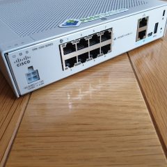
We have been asking for this for years! Even on my home network I’ve not been able to allocate an ASADHCP reservation for my laptop and my MyCloud drive. I’ve been in discussions in forums with people who are convinced that putting a static ARP entry into the ASA would solve the problem (it doesn’t – I tested it extensively!)
But finally in version 9.13(1) we can now add a static DHCP reservation (MAC address to IP address).
Then simply add the reservation, you need to specify the MAC address as xxxx.xxxx.xxxx (that’s with full stops not colons), if in doubt, ping the existing IP address then execute a ‘show arp’ command to show you all the MAC addresses the firewall can see, so you can copy/paste it into the following command;
A while ago I did a run through on site to site VPNs from Cisco ASA to Fortigate firewalls. Back then I said that the default settings were a bit ‘shoddy‘ and that I’d revisit it once I had more time.
What do you mean shoddy? Well, Cisco and Fortinet are both guilty of enabling ‘Everything’ to make the tunnel come up, so people can just use a wizard and not put to much thought into the process, for most people thats absolutely fine. However I’ve found ‘Many Times‘ I’ve been trying to put a VPN into third party and it’s like a game of ‘Encryption Bingo‘ e.g. ‘Can you change it from AES128 to AES256 and change the hash to SHA512‘, or ‘Do you not support elliptical curve’. Who are these people? Do they expect Tom Cruise to come rappelling out of a skylight to steal the details of their 2016 Christmas golf event!
I digress, so here’s how to set up a site to site VPN using IKEv2 with some weapons grade encryption. Here’s a pretty picture of what it will look like;
And here’s what my test bench topology looks like in EVE-NG.
Configuring the Fortigate for Site to Site VPN
After saying don’t use the wizard, I’m going to use the wizard to do the Fortigate end, then I’ll edit the tunnel it creates and make it a bit more ‘fit for purpose’.
From the web management portal > VPN > IPSec Wizard > Give the tunnel a name > Change the remote device type to Cisco > Next.
Give it the ‘public’ IP of the Cisco ASA > Set the port to the ‘outside’ port on the Fortigate > Enter a pre-shared key, (text string, you will need to enter this on the Cisco ASA as well, so paste it into Notepad or something for later) > Next.
Local interface will be in the ‘inside’ interface on the Fortigate > Enter the local subnet(s) > Enter the remote (behind the ASA) subnet(s) > Next.
Review the settings > Create.
Select IPSec Tunnels > Select the new tunnel > Edit.
In the Authentication Section > Edit > Change the IKE Version to 2 > Edit the Phase 1 Proposal.
Note: If you can’t see this option, change the tunnel type to custom.
You can do the first couple of steps together, but I like to do the Phase1 and Phase 2 proposals first, then tie it all up at the end. Configuration > Site to Site VPN > Advanced > IKE Policies > IKEv2 Policies > Add.
Local Passphrase: An alphanumeric string of characters (it’s a pre-shared key it must match the one you set on the Fortigate).
Remote Passphrase: Set the same at the local passphrase.
Scroll down.
Make sure your IKE Phase 1 policy is in the list, (you may have many) > IPSec proposal > Select > locate yours and add it in > OK > OK > Apply.
The last thing to do is make sure that the traffic travelling over the VPN DOES NOT get NAT translated > Firewall > NAT Rules > Select the top one > Add >Add Nat Rule Before.
Source Interface: inside
Destination Interface: outside
Source Address: any
Destination Address: {The group you created above for the network address behind the Fortinet}
Source NAT Type: Static
Disable Proxy ARP : Tick
Lookup Route Table: Tick
OK > Apply
Don’t forget to save the changes > File > Save Running configuration to flash
Finally send some interesting traffic across the VPN to bring up the tunnel.
Related Articles, References, Credits, or External Links
Continuing with my ‘Learn some Fortigate‘ theme’. One of the basic requirements of any edge firewall is site to site VPN. As the bulk of my knowledge is Cisco ASA it seems sensible for me to work out how to VPN both those firewalls together, like so;
Well that’s the pretty picture, I’m building this EVE-NG so here’s what my workbench topology looks like;
Disclaimer (Read First! Especially before posting any comments!)
Fortinet prides itself on you not needing to use the CLI, (until you actually need to use the CLI of course!) But both ends are configured using the GUI and ASDM. This is designed for the ‘Let’s just make it work, who cares what’s going on under the hood‘ generation. Which means it enables IKEv1NOTIKEv2 on the Fortigate, and BOTH IKEv1 and IKEv2 gets enabled on the Cisco ASA. Couple that with all the weak Crypto sets that get enabled, because someone might have a hardware firewall from 1981 or something! So in production I’d consider doing things a little more manually. I will post another article on the same subject, but then I’ll make the tunnel as secure as I can, (watch this space). This is an exercise in getting the tunnel up and making it work.
Tech Note: If you just use both wizards it wont work, thankfully I could debug the tunnel on the Cisco ASA to work out why. Fortinet sets all the DH groups to 5, and Cisco sets them all to 2. And Fortinet enables PFS and Cisco don’t. (They do on older versions of the OS, but not on the newer ones).
Create IKE/IPSec VPN Tunnel On Fortigate
From the web management portal > VPN > IPSec Wizard > Give the tunnel a name > Change the remote device type to Cisco > Next.
Give it the ‘public’ IP of the Cisco ASA > Set the port to the ‘outside’ port on the Fortigate > Enter a pre-shared key, (text string, you will need to enter this on the Cisco ASA as well, so paste it into Notepad or something for later) > Next.
Local interface will be in the ‘inside’ interface on the Fortigate > Enter the local subnet(s) > Enter the remote (behind the ASA) subnet(s) > Next.
Review the settings > Create.
Select IPSec Tunnels > Select the new tunnel > Edit.
Connect to the ASDM > Wizards > VPN Wizards > Site-to-Site VPN Wizard > Next.
You should already have an object for your Local Network add that in > Then add in a new Network Object for the remote (behind the Fortigate) subnet. MAKE SURE that the new object is selected as the Remote Network > Next.
Enter the Pre-Shared key you used (above) > Next > Tick to DISABLENAT > Next > Finish.
Tech Note: Look at all those Ciphers/Hashing/Additional Protocols that are about to be turned on! 🙁 That’s why I work at command line.
Finally you will need to send some traffic over the tunnel to ‘bring it up’.
If you have a problem, see the debugging/troubleshooting links below.
Related Articles, References, Credits, or External Links
Normally if I were deploying Duo 2FA with AnyConnect I’d deploy a Cisco RADIUSVPN on my LAN, (usually on my Duo Authentication Proxy). See the following article;
However, last time I set this up, a colleague said ‘Oh by the way, you don’t need to do that, you can just point the firewall directly at Duo‘. I was initially skeptical but I tried it, and it worked. I thought no more about it until this week when another colleague asked me to help him setup Duo for AnyConnect.
As you can see the firewall queries Duo using LDAPS, but the Duo product I’m using is called ‘Cisco RADIUS VPN’. This makes my networking OCD itch tremendously! (RADIUS and LDAPS are completely different protocols!) But it works, so here we go.
Solution
Note: For this solution you don’t even need to sync your users to Duo, (but it’s OK if you do)! As long as the users exist there.
With Duo, you need to select ‘protect an application‘ and select ‘Cisco RADIUS VPN‘. If you are unfamiliar with Duo you need to take a copy of the Integration Key, the Secret Key and the API Hostname. (Note: Don’t try using these ones, they have been changed!)
On the Firewall > Configuration > Device Management > Users/AAA > AAA Server Groups > AAA Server Groups > Add > Call it ‘DUO-EXTERNAL’ > Select LDAPS > OK.
With your DUO-EXTERNAL group selected > In the bottom window > Add.
TO TEST: Press Test > Select Authentication > Use the username displayed in Duo > Type push into the password box, and your phone should then prompt for 2fa authentication. (If it fails: Make sure the time is correct on the ASA, and at least do some debugging before posting below!)
Now either create a new AnyConnect profile, and use this new AAA method, or simply change the AAA method for an existing AnyConnect profile, (like below).
A word of warning, when I did this, (both in production and on my test ASA,) I got a strange error, I’ve documented that and the fix, below.
I had a call with a client last week, they are in one of my employer’s DCs, and their servers are behind a vASA. They had purchased some Meraki MX devices for their IT team who were working remotely (during the Covid-19 lockdown), and were struggling. Normally we would just suggest AnyConnect, but these guys were building new machines for their clients, and needed access directly to the domain from their home networks to facilitate this. So a Site-to-Site VPN was the ‘best fit’ for them.
But being home internet connections they were on DHCP for their public IP addresses. If we were all Meraki, then Meraki Auto VPN would have them up and running in no time. Conversely if they were all ‘proper’ Cisco we would be OK. In fact if they had static IP’s at home we would be OK.
So how to setup a site-to-site VPN ‘into’ a Cisco ASA with a static IP, from another firewall with a dynamically assigned (DHCP) public IP?
I tested this firstly using a Cisco ASA at the ‘remote/dynamic’ end, then tested with a Meraki MX Device. But the methodology can be applied to any ISAKMP/IPSEC capable firewall with a dynamically assigned public IP that you want to establish a VPN into an ASA with a static IP address.
Solution
Step 1: Investigate Your Remote Device
Do your homework on the remote device, find out what it supports for VPN connectivity, you will need to answer the following questions;
IKE Version: Does it use/support IKEv1 or IKEv2 (or both) Set the ASA config accordingly
Subnet on the remote site: Make sure it does not overlap with your central site, (or anyone else who will also be ‘dynamically’ connecting*).
Pre-Shared-Key: MAKE SURE this is long/complicated and hard to guess.
*Note This may mean your remote sites may need to change their subnets so they don’t overlap!
Step 1 Configure the ‘Central’ ASA
I’ve covered IKEv1 VPNsand IKEv2 VPNs elsewhere on the site, feel free to go and see what what the following configuration is doing. For my Meraki Tunnel I’m going to use IKEv1, Phase 1 (3DES, SHA, Diffie Hellman Group 2, and a Lifetime of 86400 Seconds,) and Phase 2 (3DES, SHA and no PFS). Note: Some would consider this weak, but it’s the default setting on the remote device so lets keep it simple. In production you can slowly make phase1/2 more secure to your liking once you know it’s working.
Change the values in Red;
WARNING: If you already have a crypto map in use then change the keyword CRYPTO-MAP (below) to match yours. (Or all your VPNs will suddenly stop working!) Issue the command show run crypto map, if you’re unsure.
I like object-groups, they can make your firewall configs a lot smaller/neater and if you need to add a host, network, range, or port, then you can simply add the new requirement to an existing group. But what if you want to allow both UDP and TCP ports, you can create a service group for TCP and add the ports and a service group for UDP and add the ports, and add them into your ACL where you would expect ports to be, (at the end of the ACL,) like so;
Note: What this actually does is create ‘destination port’ objects, if you didn’t already know, if you are connecting to a web server on port 443 (https) for example, the source port can be any port number, it’s the destination port number that is 443. (If you’ve ever worked on a Symantec/SEF/Velociraptor firewall this would be more important).
Then place that service group in the ACL where you would normally specify the PROTOCOL like so;
[box]
!
access-list inbound permit object-group OBJ-Service-Ports any host 192.168.1.10
![/box]
Much simpler!
Related Articles, References, Credits, or External Links
I recently did a post on adding extra licences to AnyConnect, (with the current surge of people working from home). I exclusively work at command line, so when I was asked how to do the same in the ASDM I had to go and check 🙂
Solution
Connect to your firewalls ASDM console, then navigate to > Configuration > Device Management > Licensing > Activation Key > Enter you new Activation Key > Update Activation Key.
Before I’m asked: Your activation key lives on the flash memory within you firewall so you should not need to save the config, (unless you have made other changes), or are prompted to do so by the ASDM, (which will know if theres any pending changes).
Related Articles, References, Credits, or External Links
I was asked to setup a VPN to help out a colleague this week. When I had a look, one end turned out to be an Edge Gateway, I wasn’t that concerned, I’d done similar things in my prior role, I just didn’t have access to the vCloud or VMware at this datacenter.
Depite my best efforts on the ASA, the tunnel refused to come up, it took a little looking ‘under the covers’ to accurately diagnose the problem. But to save you my pain, I’ll post the setup of both ends so yours will be a little less stressful.
VMware Edge Gateway VPN Setup
Locate the Edge Gateway in vCloud Director > VPN > Create new VPN > Tick ‘Enable This VPN‘ configuration > Set the local and remote networks > Local ID is the local public IP of the Edge Gateway > Remote ID is the pubic IP of the Cisco ASA > Set the encryption protocol as AES256 > Copy the pre-shared-key (Warning: some browsers wont select all of the key, and you will end up characters short, make sure you have it all!) > OK.
On the ‘Firewall’ Tab allow all traffic TO and FROM the remote subnet, (behind the Cisco ASA).
Note: There no need to make a NAT Exemption.
Cisco ASA VPN Setup (For Edge Gateway)
Note: The version of Edge Gateway I was using, was using (once AES256 is selected)
IKE Version: 1
Encryption:AES-256
Hashing: SHA
Diffie Hellman: Group 2
Perfect Forward Secrecy: Enabled (group 2)
I’m aware that newer Edge Gateways support IKEv2 but debugging the incoming requests told me mine was using IKEv1.
You DO NOT have any existing VPNs configured, (if you do, change the name of the CRYPTO-MAP (above) to match the name of your cryptomap and use a higher number, e.g. ‘outside_map 2‘).
Troubleshooting Edge Gateway End of the VPN
You need access to the underlying VMware infrastructure > Select Networking and Security > Locate the NSX Edge > VPN > IPsec VPN > Show IPsec Statistics > Here you can see some meaningful error massages if theres a problem.
Troubleshooting Cisco ASA End of the VPN
I’ve covered this to death in the past, so rather than reinvent the wheel;
I was asked if I’d ever set this up the other week. Surprisingly I had not, I’d deployed Duo for other things, but not for Cisco AnyConnect. As I had some other ‘Duo’ related tasks coming up, I was deploying it on the test bench, then adding in my Cisco ASA and AnyConnect wasn’t much more work!
Here’s my topology;
My ASA is running version 9.1
My Duo Authentication Proxy is installed on Windows 2019
I’m running Cisco AnyConnect Version 4.8
Cisco AnyConnect Duo Pre-Requisites
I already have a Duo Authentication Proxy server setup and my users are enrolled, you will need to set this up first. See the following article;
Log into the the Duo Admin Portal > Applications > Protect an Application > Search for and select Cisco RADIUS VPN > Copy the Integration Key, Secret Key and the API hostname to notepad.
Back on your Duo Authentication Proxy, (because you completed the pre-requisites) add the following to the bottom of your authproxy.cfg file;
Note: 192.168.254.254 is the inside interface of the Cisco ASA, and 666999 is the shared secret we will enter on the firewall in a moment. I’m not sure you have to, but at this point I’d restart the Duo Auth Proxy service as well.
Configure Cisco ASA for Duo RADIUS
Log into the ASDM > Configuration > Device Management > Users/AAA > AAA Server Groups > Add.
You only need to add the name of the server group i.e DUO-RADIUS, and ensure protocol is set to RADIUS > OK > Apply.
Now select the DUO-RADIUS group in the top window, and click ‘Add’ in the bottom window > Specify the interface that’s facing the Duo Auth Proxy Server > Add its IP address > Change the Timeout to 60 seconds > Set the Server Authentication port to 1812 > Set the Server Accounting Port to 1813, (though it will NOT do accounting) > Type in the Secret Key you specified above > Untick Microsoft CHAPv2 Capable > OK.
Testing Cisco ASA Duo 2FA Authentication
I’ve written about testing AAA before in the following article;
But essentially with the SERVER selected > Test > Select Authentication > Enter the username and password for a user.
What about passcodes and 2FA? This will send a push notification to the users Duo Authenticator (phone), you can enter the password then a comma, then the passcode from the Duo App if you wish, I just prefer the push notification).
Note: This is for Cisco ASA 5500, 5500-x, and Cisco Firepower devices running ASA Code.
Note2: If your firewall is running a version older than 8.3 you will need to scroll down the page.
Port forwarding on Cisco firewalls can be a little difficult to get your head around, to better understand what is going on remember in the “World of Cisco” you need to remember two things…..
1. NAT Means translate MANY addresses to FEW Addresses
2. PAT Means translate MANY addresses to ONE Address.
Why is that important you ask? Well most networking types assume NAT is translating one address to many, BUT on a Cisco device this is PAT, and it uses (as the name implies) port numbers to track everything. e.g. the first connection outbound might be seen on the firewall as 123.123.123.123:1026 and the second connection outbound might be seen as 123.123.123.123:2049 so when the traffic comes back the firewall knows where to send it.
Fair enough but what has that got to do with Port Forwarding? Well you can use the exact same system to lock a port to an IP address – so if only one port can go to one IP address then that’s going to give you port forwarding 🙂
To make matters more confusing (sorry) you configure PAT in the NAT settings, for this very reason it confuses the hell out of a lot of people, and the GUI is not intuitive for configuring port forwarding, (the ADSM is better than the old PIX PDM) but most people, (me included,) prefer to use command line to do port forwarding.
Note: This option uses ASDM Version 7.9(2) If yours is older see below;
Connect to the ASDM, Configuration > Firewall > NAT Rules > Right Click ‘Network Object Nat Rules’ > Add ‘Network Object’ Nat Rule.
Name = “Give the internal server/host a sensible name” > Type = Host > IP Address = The internal / private IP address > Type = Static > Translated address = Outside > Advanced > Source Interface = Inside > Destination Interface = Outside > Protocol = TCP > Real port = http > Mapped Port = http > Ok > OK > Apply.
Note: This assumes your Outside interface is called outside, Inside interface is called inside and you want to port TCP port 80 (http).
Interface = Outside > Action = Permit > Source = Any > Destination {Browse} > Locate the object you created earlier > Add to Destination > OK.
Service {Browse} > Select the Port you require (i.e. http) > OK.
OK > Apply > When you have tested it works, save the changes.
Using Older ASDM (PIX V7 and ASA5500) 1 Port to 1 IP Address
1. As above you will need to know the port and the IP to forward it to, Launch the ASDM, Select Configuration > Security Policy > Then either Rule Add, or right click the incoming rules and select “Add Access Rule.”
2. Interface = Outside > Direction = Incoming > Action = Permit > Source = Any > Destination, Type = Interface IP, Interface = Outside > Protocol = TCP > Destination Port Source = smtp (for example) > OK > Apply.
3. Back at the main screen select Configuration > NAT > Add, or Right Click an Existing mapping and click “Add Static NAT Rule.”
4. Real Address Interface = Inside > IP Address = 10.254.254.1 > Netmask = 255.255.255.255 > Static Translation Interface = outside > IP Address = (Interface IP) > Tick “Enable Port Translation (PAT) > Protocol = TCP > Original Port = smtp > Translated Port = smtp (for example) > OK > Apply.
5. File > “Save Running Configuration to Flash.”
Option 2 Use the Command Line to Port Forward (Post Version 8.3)
Note: Port forwarding changed on PIX/ASA devices running OS 8.3 and above, in regards to port forwarding. There is no longer a global command, for a full run-down of the changes click here.
If you issue a global command after version 8.3 you will see this error,
ERROR: This syntax of nat command has been deprecated.
Please refer to “help nat” command for more details.
1. First things first, you will need to know what port you want to forward, and where you want to forward it, for this example We will assume I’ve got a server at 10.254.254.5 and it’s a mail server so I want to Forward all TCP Port 80 traffic (HTTP) to it. Connect to the Firewall via Console/Telnet or SSH.
[box]
Warning Notice
User Access Verification#
Password:********
Type help or '?' for a list of available commands.
Petes-ASA>
[/box]
2. Enter enable mode, and enter the enable mode password.
[box]
Petes-ASA> enable
Password:********
Petes-ASA#
[/box]
3. Now we need to go to configuration mode.
[box]
Petes-ASA# configure terminal
Petes-ASA(config)#
[/box]
4. Create an object for the web server that the traffic is going to be forwarded to.
6. Now you need to allow the http traffic in. Before you can add an ACL you need to see if you already have one. We are applying an ACL to the outside interface for traffic going in (I call this inbound for obvious reasons). To see if you already have an ACL applied, issue the following command;
[box]
Petes-ASA# show run access-group
access-group inbound in interface outside
access-group outbound in interface inside
[/box]
Note: In the example above we have an ACL called inbound that we MUST use. (If you added a new one, all the access list entries for the old one get ‘Un-applied’). If yours has a different name (e.g. outside_access_in then use that instead of the ACL name I’m using here). If you DONT have an access-group entry for inbound traffic then we will do that at the end!
[box]
Petes-ASA(config)# access-list inbound permit tcp any object Internal_Web_Server eq http
[/box]
7. Then: Only carry out the following command if you DO NOT HAVE an ACL applied for incoming traffic.
[box]
Petes-ASA(config)# access-group inbound in interface outside
Petes-ASA(config)#
[/box]
8. Don’t forget to save your hard work. (write memory).
object network Internal_Web_Server
host 10.254.254.5
nat (inside,outside) static interface service tcp http http
access-list inbound permit tcp any object Internal_Web_Server eq http
access-group inbound in interface outside
[/box]
Use the Command Line to Port Forward (pre version 8.3) 1 Port to 1 IP Address
1. First things first, you will need to know what port you want to forward, and where you want to forward it, for this example we will assume I’ve got a server at 10.254.254.1 and it’s a mail server so I want to forward all TCP Port 25 traffic to it. Connect to the Firewall via Console/Telnet or SSH.
[box]
Warning Notice
User Access Verification
Password:*******
Type help or '?' for a list of available commands.
Petes-ASA>
[/box]
2. Enter enable mode, and enter the enable mode password.
[box]
Petes-ASA> enable
Password: ********
Petes-ASA#
[/box]
3. Now we need to go to configuration mode.
[box]
Petes-ASA# configure terminal
Petes-ASA(config)#
[/box]
4. Now you need to allow the http traffic in. Before you can add an ACL you need to see if you already have one. We are applying an ACL to the outside interface for traffic going in (I call this inbound for obvious reasons). To see if you already have an ACL applied, issue the following command;
[box]
Petes-ASA#show run access-group
access-group inbound in interface outside
access-group outbound in interface inside
[/box]
Note: In the example above we have an ACL called inbound that we MUST use. (If you added a new one, all the access list entries for the old one get ‘Un-applied’). If yours has a different name (e.g. outside_access_in then use that instead of the ACL name I’m using here). If you DON’T have an access-group entry for inbound traffic then we will do that at the end!
5. Then: Only carry out the following command if you DO NOT HAVE an ACL applied for incoming traffic.
[box]
Petes-ASA(config)# access-group inbound in interface outside
Petes-ASA(config)#
[/box]
6. Lastly the command that actually does the port forwarding, (static command). And allow the traffic in.
Option 3 Use the PIX Device Manager (PIX Version 6 Only)1 Port to 1 IP Address
1. As above you will need to know the port and the IP to forward it to, Launch the PIX Device manager, Select Configuration > Access Rules > Then either click “Rule”s > Add or Right click an incoming rule and select > “Insert Before” or “Insert After”.
2. Under the “Action” select “Permit”, Under Source Host/Network Select “Outside”, and all the zeros, Under Destination Host/Network Select “Inside” and all the zeros then set the “Destination Port” to smtp > OK > Apply.
3, Now select the “Translation Rules” tab, Rules Add or Right click a rule and select “Insert before” or “Insert After”.
4. In this example I’ve set it to forward all TCP Port 25 traffic to 10.254.254.10 (NOTE: I’ve blurred out the public IP Address you will need to add this also) > OK > Apply.
5. Finally save your work > File > “Save Running Configuration to Flash.” > Exit.
Related Articles, References, Credits, or External Links