ASA Setup FirePOWER Services (for ASDM)

KB ID 0001107 

Problem

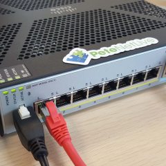
Both the 5506-X (rugged version and wireless), and 5508-X now come with a FirePOWER services module inside them. This can be managed from either ASDM* (with OS and ASDM upgraded to the latest version), and via the FireSIGHT management software/appliance.

Related Articles, References, Credits, or External Links

*UPDATE: All ASA ‘Next-Gen’ firewalls can now have their Firepower Service Module managed from the ASDM.

Solution

1. The first thing to do is cable the management interface and the interface you are going to use as the ‘inside’ (LAN) into the same network (VLAN).

2. The next step might seem strange if you are used to working with Cisco firewalls, but you need to make sure there is no IP address configured on the management interface. Try to think of it as just the hole that the FirePOWER services module (which will get its own IP) speaks out though.

[box]

Petes-ASA# configure terminal
Petes-ASA(config)# interface Management1/1
Petes-ASA(config-if)# no nameif
WARNING: DHCPD bindings cleared on interface 'management', address pool removed
Petes-ASA(config-if)# no security-level
Petes-ASA(config-if)# no ip address 

[/box]

3. So it should look like this;

[box]

Petes-ASA(config-if)# show run
: Saved

ASA Version 9.3(2)2
!
----Output removed for the sake of brevity----
!
interface Management1/1
management-only
no nameif
no security-level
!
----Output removed for the sake of brevity---- 

[/box]

4. Lets make sure the FirePOWER service module is ‘up’ and healthy.

[box]

Petes-ASA(config)# show module 


Mod  Card Type                                    Model              Serial No.

---- -------------------------------------------- ------------------ -----------

   1 ASA 5506-X with FirePOWER services, 8GE, AC, ASA5506            JAD19090XXX

 sfr FirePOWER Services Software Module           ASA5506            JAD19090XXX


Mod  MAC Address Range                 Hw Version   Fw Version   Sw Version

---- --------------------------------- ------------ ------------ ---------------

   1 a46c.2a99.eec5 to a46c.2a99.eece  1.0          1.1.1        9.3(2)2

 sfr a46c.2a99.eec4 to a46c.2a99.eec4  N/A          N/A          5.4.1-211


Mod  SSM Application Name           Status           SSM Application Version

---- ------------------------------ ---------------- --------------------------

 sfr ASA FirePOWER                  Up               5.4.1-211


Mod  Status             Data Plane Status     Compatibility

---- ------------------ --------------------- -------------

   1 Up Sys             Not Applicable

 sfr Up                 Up

[/box]

5. The SFR module is actually a Linux box that’s running within the firewall, to connect to it you issue a ‘session sfr’ command.

  • Default Username: admin
  • Default Password: Sourcefire (capital S)
  • Default Password (after version 6.0.0): Admin123 (capital A)

As this is the first time you have entered the SFR you need to page down (press space) though the sizable EULA, then accept it.

[box]

Petes-ASA(config)# session sfr
Opening command session with module sfr.
Connected to module sfr. Escape character sequence is 'CTRL-^X'.
Cisco ASA5506 v5.4.1 (build 211)

Sourcefire3D login: admin

Password: Sourcefire

Copyright 2004-2015, Cisco and/or its affiliates. All rights reserved.
Cisco is a registered trademark of Cisco Systems, Inc.
All other trademarks are property of their respective owners.

Cisco Linux OS v5.4.1 (build 12)

Cisco ASA5506 v5.4.1 (build 211)

You must accept the EULA to continue.

Press <ENTER> to display the EULA:

END USER LICENSE AGREEMENTIMPORTANT: PLEASE READ THIS END USER LICENSE AGREEMENT CAREFULLY. IT IS VERY

----Output removed for the sake of brevity---- 

Product warranty terms and other information applicable to Cisco products are

available at the following URL: http://www.cisco.com/go/warranty.
----Output removed for the sake of brevity---- 

Please enter 'YES' or press <ENTER> to AGREE to the EULA: YES

[/box]

6. Set a new password.

[box]

System initialization in progress. Please stand by.
You must change the password for 'admin' to continue.

Enter new password: Password123

Confirm new password: Password123

[/box]

7. Set up all the IP and DNS settings, then exit from the module session.

[box]

You must configure the network to continue.
You must configure at least one of IPv4 or IPv6.

Do you want to configure IPv4? (y/n) [y]: y
Do you want to configure IPv6? (y/n) [n]: n
Configure IPv4 via DHCP or manually? (dhcp/manual) [manual]: manual
Enter an IPv4 address for the management interface [192.168.45.45]: 192.168.100.22
Enter an IPv4 netmask for the management interface [255.255.255.0]: 255.255.255.0
Enter the IPv4 default gateway for the management interface []: 192.168.100.1
Enter a fully qualified hostname for this system [Sourcefire3D]: SFire
Enter a comma-separated list of DNS servers or 'none' []: 192.168.100.10,192.168.100.11
Enter a comma-separated list of search domains or 'none' [example.net]: petenetlive.com,pnl.net

If your networking information has changed, you will need to reconnect.

For HTTP Proxy configuration, run 'configure network http-proxy'

Applying 'Default Allow All Traffic' access control policy.
You can register the sensor to a Defense Center and use the Defense Center

----Output removed for the sake of brevity---- 

sensor to the Defense Center.

> exit

Remote card closed command session. Press any key to continue.

[/box]

8. Now you need to ‘send’ traffic though the module, in this case I’m going to send all IP traffic though, I’m also going to set it to ‘fail open’, If you set it to fail closed then traffic will cease to flow though the firewall if the FirePOWER services module goes off-line. I’m making the assumption you have a default policy-map applied.

[box]

Petes-ASA(config)# access-list SFR extended permit ip any any
Petes-ASA(config)# class-map SFR
Petes-ASA(config-cmap)# match access-list SFR
Petes-ASA(config-cmap)# exit

[/box]

9. Add that new class-map to the default policy-map.

WARNING: If you are going to set ‘fail-close‘ then make sure your SFR module is operating normally, or you will cause downtime, best to do this in a maintenance window!)

[box]

Petes-ASA(config)# policy-map global_policy 
Petes-ASA(config-pmap)# class SFR
Petes-ASA(config-pmap-c)# sfr fail-open
Petes-ASA(config-pmap-c)# exit
Petes-ASA(config-pmap)# exit

[/box]

10. Save the changes.

[box]

Petes-ASA(config)# write mem
Building configuration...

Cryptochecksum: 72c138e3 1fa6ec32 31c35497 621cff02

35819 bytes copied in 0.210 secs

[OK]

[/box]

11. At this point the firewall should be able to ping the management IP of the SFR module.

[box]

Petes-ASA# ping 192.168.100.22
Type escape sequence to abort.
Sending 5, 100-byte ICMP Echos to 192.168.100.22, timeout is 2 seconds:
!!!!!
Success rate is 100 percent (5/5), round-trip min/avg/max = 1/2/10 ms
Petes-ASA#

[/box]

12. Now when you connect to the ASDM you can manage the FirePOWER services module.Note: I have seen some firewalls that flatly refuse to connect to the Firepower Services Module, and give an error ‘unable to connect on port 443’ every time you launch ASDM. I just re-image the module and load in a fresh install (40 mins to an hour), and start again.

Code to Copy & Paste

If you are lazy like me!

[box]

access-list ACL-FirePOWER extended permit ip any any
 class-map CM-SFR
 match access-list ACL-FirePOWER
 exit
policy-map global_policy 
 class CM-SFR
 sfr fail-open
 exit
 exit
write mem

[/box]

Note If you get an unable to connect error see the following article;

Cisco – Cannot Connect to the ASA FirePOWER Module

13. I suggest you update everything first, the ASA will configure an access control policy set to allow and inspect all traffic by default, which we will edit, set everything to update on a schedule, (rule updates and geolocation info).

Cisco FirePOWER Services Adding Licences (ASDM)

In the box with the firewall, you will have an envelope, you don’t need to open it (as below) because the PAK number you need is printed on the outside anyway. This is the firewalls CONTROL LICENCE, it allows it to be managed, we will install it into the ASDM, if you have a SourceFIRE appliance to manage the firewall you would install it there. You need two  bits of information the PAK and the LICENCE KEY of the FirePOWER module, (See Below).

The Licence Key is the MAC address of the Module, (Not the ASA). You can find it at Configuration > ASA FirePOWER Configuration > Licence. This is also where you will add all the licences. Go to www.cisco.com/go/licence and register the licence (and any additional licences i.e. AMP, Web filtering, etc.)

The Licence(s) will be emailed to you open them in a text editor and copy the text of each licence. You can see I’ve indicated below what you should be copying.

Paste that into the ASDM > Submit Licence.

It should say success, if it fails you’ve pasted to much text, or there’s a problem with the licence.

Review you licences, here Ive added AMP and web filtering but Ive yet to add the control licence. If you don’t add the control licence then when you try and edit the access control policy it will say you need a PROTECTION LICENCE (confusingly!)

FirePOWER Services Setup IPS

Disclaimer: These settings, (and allotters below,) are to get you up and running, As with any security device, you need to tune settings accordingly. Please don’t follow these instructions, then email me with complaints that you been attacked by ISIS/Scammers/Bots etc.

You get an IPS/IDS Licence with any of the subscription based licences, its less hassle to set this up before the the access control policy. Configuration > ASA FirePOWER Configuration  > Policies > Intrusion Policy  > Create Policy > Give it a name > I tend to use ‘Balanced Security and connectivity’ look at the other options and choose whichever you prefer > Create and Edit Policy.

Give the policy a name > Commit changes (I accept all the defaults).

FirePOWER Services Enable Malware Inspection and Protection

Note: Obviously this needs you to have added an AMP Licence!

 Configuration > ASA FirePOWER Configuration  > Policies > Intrusion Policy  > Files > New File Policy > Give it a name > Store FirePOWER Changes.

Add new file rule > I add everything  > and Set it to ‘Block Malware’ > Store FirePOWER Changes.

“Store ASA FirePOWER Changes”.

Warning: Nothing will be inspected, until you add this file policy to an access control policy.

ASA FirePOWER Services Edit / Create Access Control Policy

I renamed the default policy, Note: Even though I’ve called it ‘Base-Access-Control-Policy’ you can only apply one policy, you just add different rules to the policy as required. Add Rule.

In Source Networks > Add in ‘Private Networks’ (See Warning Below).

Inspection Tab > Add in the IPS and file policy you created above (That’s why I’ve done it in this order).

I set it to log at the end of the connection  > Add.

“Store ASA FirePOWER Changes”.

FirePOWER Private Networks Warning

Private networks only cover RFC1918 addresses, if you LAN/DMZ etc subnets are different you should create a new Network object, then add the subnets for your network. If you do this, then substitute your network object every time I mention the Private Networks object.

Blocking a Particular URL with FirePOWER Services

Even if you don’t have a Web Filtering licence you can block particular URL’s here Im going to block access to Facebook.  Configuration > ASA FirePOWER Configuration  > Object Management > URL > Individual Objects > Add URL > Note Im adding http and https.

Then add a rule to your existing access control policy ABOVE the permit all rule, (they are processed like ACLS from the top down). Set the source network to your private subnets.

On the URLs tab add in your URL objects and set the action to block with reset, or Interactive block with reset if you want to let the users proceed to Facebook after a warning.

Note: If you have a Web filtering Licence you can select ‘Social Networking’ from the Categories tab, and that would also block Facebook, and Twitter etc.

ASA FirePOWER Services Commit and Deploy The Changes

FirePOWER services behaves the same on-box as it does when you use the SourceFIRE Appliance, you can make changes but nothing gets deployed until you commit the changes. If you have made a change then there will be a ‘Store ASA FirePOWER services button active. Then you need to select File > Deploy FirePOWER Changes.

Note: You will only see the Deploy option on SFR modules running 6.0.0 or newer.

Deploy.

Even now its not deployed, it takes a while, to see progress navigate to Monitoring > ASA FirePOWER Monitoring > Task Status > It will probably have a ‘running’ task.

Wait until the policy deployment says completed before testing.

Related Articles, References, Credits, or External Links

Originally Published 17/11/15

Thanks to Eli Davis for the feedback.

Cisco ASA 5506-X / 5508-X Restart the FirePOWER Service Module

HP StorageWorks P2000 – Connecting to and Configuring

KB ID 0000569 

Problem

Normally I simply connect a new MSA to a clients network, and it gets it’s address from DHCP. Then I can get the address for the DHCP Scope, and point my web browser at it.

Yesterday I was starting with new virtual infrastructure and had no DHCP. With the G1 and G2 models, you got a console/serial cable and could just terminal in. With the G3 they have replaced the serial socket with a mini USB socket. Each time I put in a new P2000, I think “I wonder how that USB CLI socket works?” Yesterday I had to find out.

Solution

The Quickest Solution – is to connect the MSA to the network, and if it cannot get a DHCP address it automatically gives itself 10.0.0.2/24 on controller A and 10.0.0.3/24 on controller B.

MSA Default username = manage
MSA Default password = !manage

The Next Quickest Solution

1. If you do have DHCP running, connect your MSA and run the MSA Device Discovery Tool, (On the CD that came with the device).

2. Once you know the IP address, you can connect with your web browser.

Connect to and Manage your MSA via the USB/CLI Cable

1. For your machine to see the MSA as a device, you need to install a driver, there is a copy of the drivers on the CD that came with the device.

Note: Windows 7 users, use the Windows 2008 Drivers or use this one.

2. Install the driver.

3. Connect the USB lead from the MSA controller to your machine, TAKE NOTE of the COM port number it’s using.

4. Now you can use whatever terminal emulation program you prefer to connect to that COM port. (I prefer HyperTerminal, or you can use Putty if you want something a bit lighter).

5. Set the following, Bits per second = 115200, Data bits = 8, Parity = None, Stop bits = 1, and Flow control = None.

6. You will need to press {enter} to connect, then login.

MSA Default username = manage
MSA Default password = !manage

7. I only need to set the IP address of the controller(s) like so;

[box] set network-parameters ip {x.x.x.x} netmask {y.y.y.y} gateway {z.z.z.z} controller a [/box]

8. Then (If you have dual controllers) you can set the IP address of controller B.

[box] set network-parameters ip {a.a.a.a} netmask {b.b.b.b} gateway {c.c.c.c} controller b [/box]

9. Give the new IP addresses a quick test.

10. Note: You Cannot Manage an G3 P2000 with Internet Explorer 9, If you try it will simply say “Unable to Authenticate, Try again”

11. Normally I use Chrome, but that won’t work either 🙁 Firefox works fine though!


Related Articles, References, Credits, or External Links

NA


Brocade 300 SAN Switch – Setup and Configure

KB ID 0000593

Problem

I got a warning from a colleague that these switches, were no longer ‘Open’. i.e. You can no longer just plug them in, connect all your SAN devices and it will work. That’s how they used to work, so someone has decided to have then ‘Not Work’ out of the box (Nice one, well done).

Solution

Rack fitting the Brocade 300 SAN Switch

1. Each mounting rail is in three pieces (2 long pieces and a small bracket that will be in the bag with the screws). The two outer brackets (without all the screw holes in them) are labelled left and right, and are fixed to the front of the rack, using the square washers that fit into the square holes in the rack, (see below).

2. At the rear, use the small bracket and screw it to the rack in the same manner as the front.

3. The ‘inner’ rails screw onto the side of the switch and the air guide/baffle, as shown. If you line the front up the correct screw holes should be visible. Secure them with the round headed screws that have washers on them. (Note: the air baffle has a row of rivets on it – these face downwards).

4. With both inner rails fitted, the switch will slide into the outer rails that are screwed to the rack. (From the front you want the power socket on the left, or the switch will go in upside down!)

5. Once inserted secure in place with a single screw in the middle.

5. Finally, use the large nut to secure all the rails to the bracket at the rear.


Configuring the Brocade 300 SAN Switch

If you are feeling especially lazy, you can connect the switch to the network and connect to it via http://10.77.77.77 (Give yourself an IP address of 10.77.77.1/24). Use the username root and the password fibranne

1. If you don’t want to do that, connect the console cable (provided) to your PC and launch the EZ Setup Software supplied with the switch. Select English > OK.

2. At the Welcome Screen > Next > Next > accept the EULA > Install > Done > Select Serial Cable > Next > Next (make sure HyperTerminal is NOT on or it will fail). It should find the switch > Set its IP details)

2. Next > Follow Instructions.

3. With the IP address set, you can connect to the switch via its web console (You must have Java installed). Once logged in (the default root password id fibranne unless you have changed it). Select ‘Zone Admin’.

4. Select Zone > New Zone > Create one > Now select all the WWW/Node names that are connected, and then you can add then to the new zone.

5. Before closing the window, Zoning Actions > Save Config.

Brocade 300 Additional Notes

Whilst connected via terminal (9600/8/1/N) you can use the following commands;

To show IP “ipaddshow”
To change IP “ipaddrset”

Default Passwords

username root password fibranne
username admin password password

Related Articles, References, Credits, or External Links

NA