Avaya / Nortel Switch Notes

KB ID 0001285 

Problem

I don’t often use Nortel (now Avaya) switches, I know they are decent, but in my day job I usually work on Cisco, occasionally HP, and other cheap assorted nastiness switches.

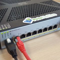
I was replacing an old 10/100 Cisco 3750 switch with a Nortel 4526GTX this week, and thought I’d take some notes for the common things I do, just in case I have to do another.

So this post is an eclectic collection of the various things I had to do, and worked out for the future.

Solution

I’m carrying the following out via console cable, the settings are the same as you would expect for a Cisco/HP switch, i.e. 

  • 9600 Baud
  • 8 bits
  • 1 stop bit
  • No Parity

WARNING: The console cable is NOT the same pinout as a normal console cable, it’s a straight through cable, (not a rollover cable). Though I did discover that the Cisco SMB switches also use the same cable.

Console: When connected it may look like nothing is happening, pressing enter etc shows no output. This is normal, you need to press CTRL+Y before you will get to command prompt.

Nortel / Avaya Switches Update the Firmware / Software

WARNING: Requires downtime, (2x reboots).

Nortel /  Avaya switches have a software image and a firmware file. ALWAYS update the firmware first! I’ve got a TFTP server setup on my laptop (see links below). With the firmware and software image files ready.

[box]

CTRL+Y 
enable 
download address {IP-address-of-TFTP-Server} diag {xxxx_xxxx_diag.bin}

[/box]

The switch will download the firmware, upgrade it and perform a reboot. When it’s back online perform the same procedure for the software image.

[box]

CTRL+Y 
enable 
download address {IP-address-of-TFTP-Server} image {xxxx_xxxxxxx_.img}

[/box]

Once again the switch will reboot, when it’s back online check the firmware, and software versions are correct on the welcome screen.

Backing up and Restoring Nortel / Avaya Switches via TFTP

I’m usually doing this for other switch vendors and for those I will backup the config to a readable text file, that I can also revert to to see how things are configured. You can do the same thing on a Nortel / Avaya switch, but YOU CANT restore the firewall from  that ‘readable’ backup, (unless you copy and paste the commands back in). To backup to a human readable file use the following  command;

[box]

copy running-config tftp address {IP-address-of-TFTP-Server} filename {File-Name}

[/box]

Well that’s all well and good, but to produce a file you can ‘restore’ the firewall from, you need to backup and restore the ‘code’. 

Backup Nortel / Avaya

[box]

copy config tftp address  {IP-address-of-TFTP-Server} filename {File-Name}

[/box]

Restore Nortel / Avaya

This reboots the switch!

[box]

copy tftp config address  {IP-address-of-TFTP-Server} filename {File-Name}

[/box]

Factory Reset Nortel Avaya Switches

As I mentioned above, I’m working on a 4526GTX switch, but the procedure is the same for;

  • 400 Series, (450, 460, 470.)
  • 2500 Series.
  • 4500 Series.
  • 5500 Series, ( 5510, 5520, 5530.)

Connect to the switch using a serial connection (settings above), then reboot the switch. If you watch the boot text, eventually it will say “Press Control C to Enter Diag” > Press Control+C > Choose option ‘i’ initiate config flash.

Then choose option ‘a’ to run agent code > The switch will now boot up.

Press CTRL+Y and the switch will have a blank, (factory reset) config.

Nortel / Avaya Set a Management IP (and Default Route)

Like other vendors, if you are going to deploy the switch in a ‘flat’ network (i.e. all ports in VLAN 1) then you only need to set up an IP address for for VLAN1. 

By default the switch will be on 192.168.1.1 which you can see with the following command;

[box]

4526GTX(config-if)#show ip
Bootp/DHCP Mode: Disabled

                      Configured        In Use         Last BootP/DHCP
                    --------------- --------------- --------------------
Stack IP Address:   192.168.1.2                       0.0.0.0
Switch IP Address:  192.168.1.1     192.168.1.1    0.0.0.0
Switch Subnet Mask: 255.255.255.0   255.255.255.0  0.0.0.0
Default Gateway:    0.0.0.0          

[/box]

To change that, first I’m going to rename VLAN, then remove that IP, and finally, set a new one.

[box]

4526GTX(config)#vlan name 1 Default-VLAN
4526GTX(config)#interface vlan 1
4526GTX(config-if)#no ip address 192.168.1.1 255.255.255.0
4526GTX(config-if)#ip address 192.168.254.1 255.255.255.0

[/box]

To set the default route, first I’m enabling routing, then setting the default route;

[box]

4526GTX(config)#ip routing
4526GTX(config)#ip route 0.0.0.0 0.0.0.0 192.168.254.254 1

[/box]

Nortel / Avaya Allowing Remote Management

This looks a little ‘Juniper SRX ‘ish”. Below the usernames will remain RW and RO. 

DONT set the RO and RW passwords the same!

To set the passwords;

[box]

4526GTX(config)#username RO Re@d0nly ro
4526GTX(config)#username RW P@ssw0rd123 rw

[/box]

Then to enable telnet, (and SSH strangely), using local authentication’

[box]

4526GTX(config)#cli pass telnet local

[/box]

Note: I didn’t have to add any extra commands to enable web management via the GUI.

Nortel / Avaya Assigning Ports to VLANS

At command line this can get a little confusing, my colleagues point out that it’s much simpler to do in the web interface. But at PNL we don’t work on the web interface.

To understand how it works, you need to remember; ‘Any port can be ‘tagged’ in a vlan, (or any number of vlans). but a port can only be untagged in one vlan‘. This is the same for all vendors, they just use different terminology i.e. HP=Tagged and Untagged, (simple). Cisco=Access Port and Trunk, (simple if you are used to it).

Unlike ‘modern‘ Cisco switches, if you reference a VLAN that does not exist, it will just error, like older switches you need to create the VLAN and add it to the VLAN database first.

Creating and Naming a VLAN

Here I create VLAN 100, and call it PROD-NW.

[box]

4526GTX(config)#vlan create 100 name PROD-NW type port

[/box]

Assign an IP Address (SVI) to a VLAN

Using the VLAN I created above, I’m adding ip address 192.168.100.1/24 to it. 

[box]

4526GTX(config)#interface vlan 100
4526GTX(config-if)#ip address 192.168.100.1 255.255.255.0

[/box]

Adding Ports to VLANS

Remember what I said above about VLANs, (a port can be tagged in multiple VLANS.) If you are a Cisco-head a port with multiple VLAN tags is a trunk. (If all the HP engineers are confused at this point, read the link a the bottom of the page).

So you need to ‘Remove’ a port from VLAN1 (or the VLAN it is in) then make it a member of your new VLAN, and finally you need to assign the PVID of your new VLAN to the port! 

So below I’m moving ports 1 to 4 into VLAN 100 from VLAN 1;

[box]

4526GTX(config)#vlan members remove 1 1-4 
4526GTX(config)#vlan members add 100 1-4 
4526GTX(config)#vlan ports 1-4 pvid 100

[/box]

Note: If you do it in the wrong order and get a warning you can stop the warnings with a ‘vlan configcontrol flexible‘ command.

To prove it worked;

[box]

4526GTX(config)#show vlan int info
      Filter     Filter
     Untagged Unregistered
Port  Frames     Frames    PVID PRI    Tagging    Name
---- -------- ------------ ---- --- ------------- --------------
1    No       Yes          100  0   UntagAll      Port 1
2    No       Yes          100  0   UntagAll      Port 2
3    No       Yes          100  0   UntagAll      Port 3
4    No       Yes          100  0   UntagAll      Port 4
5    No       Yes          1    0   UntagAll      Port 5
6    No       Yes          1    0   UntagAll      Port 6
7    No       Yes          1    0   UntagAll      Port 7
8    No       Yes          1    0   UntagAll      Port 8
9    No       Yes          1    0   UntagAll      Port 9
10   No       Yes          1    0   UntagAll      Port 10
11   No       Yes          1    0   UntagAll      Port 11
12   No       Yes          1    0   UntagAll      Port 12
-----------Config Removed for the Sake of Brevity----------

[/box]

You can also use the following command;

[box]

4526GTX(config)#show vlan
Id  Name                 Type     Protocol         PID      Active IVL/SVL Mgmt
--- -------------------- -------- ---------------- -------- ------ ------- ----
1   Default-VLAN         Port     None             0x0000   Yes    IVL     Yes
        Port Members: 5-26
100 PROD-NW              Port     None             0x0000   Yes    IVL     No
        Port Members: 1-4
Total VLANs: 2

[/box]

Or if you are running a newer version of the code;

[box]

4526GTX(config)#show run mod vlan
! Embedded ASCII Configuration Generator Script
! Model = Ethernet Routing Switch 4526GTX
! Software version = v5.6.3.025
!
! Displaying only parameters different to default
!================================================
enable
configure terminal
!
! *** VLAN ***
!
vlan create 100 type port 1
vlan name 1 "Default-VLAN"
vlan name 100 "PROD-NW"
vlan configcontrol flexible
vlan members 1 5-26
vlan members 100 1-4
vlan ports 1-4 pvid 100
no auto-pvid
!
! *** VLAN Phase 2***
!

[/box]

Other Quick Examples

[box]

Create VLAN 200 named 8021x-NW, with SVI of 192.68.100.1 and add ports 13 to 16

vlan create 200 name 8021x-NW type port
vlan members remove 1 13-16
vlan members add 200 13-16
vlan ports 13-16 pvid 200
int vlan 200
 ip address 192.168.200.1 255.255.255.0
 exit

Create a VLAN 101 named DMZ-NW, and add ports 7 to 10

vlan create 101 name DMZ-NW type port
vlan members remove 1 7-10
vlan members add 101 7-10
vlan ports 7-10 pvid 101

Add Ports 5 and 6 to (Existing) VLAN 100

vlan members remove 1 5-6
vlan members add 100 5-6
vlan ports 5-6 pvid 100

[/box]


Related Articles, References, Credits, or External Links

Special thanks for Kevin Almond, for his assistance.

Install and Use a TFTP Server

MAC OS X TFTP Software

CentOS – Install and Configure a TFTP Server

HP and Cisco – VLANs and Trunks Confusion!

Installing the Hyper-V Management Tools

Pete’s Adventures in Hyper-V Part 2

KB ID 0000093 Dtd 10/11/09

Problem

Back in Part 1 we looked at getting your Hyper-V Media up to date, the next logical step would be to install Hyper-V, but I’ve never been that logical, and I already had a Hyper-V server at home, So I thought before I went any further I would install the Hyper-V Management tools on My laptop, then I could continue this from the comfort of my sofa.

In an ideal world that would have taken about 5 minutes and then I could get back to doing things in a logical order, BUT it turned out to be such a trip round the houses I thought I’d better do this first.

Why simply installing a management console has to be so difficult I don’t know, I’ve read many posts on other sites and forums, where it “Just Worked” but mine didn’t so lets take the worse case scenario and deal with that.

Before you start you need…….

1. A machine running Vista WITH SP1 installed

2. The Hyper-V management update, there’s a sea of dead links in the internet for these x86 or x64

3. The RSAT Tools Installed CLICK HERE

Solution

1. Assuming you have installed the RSAT already > Put the administrative tools on your start menu > Right click the taskbar > Properties > Start menu > Customize > System Administrative Tools > Display on the all programs and start menu.

Note: I add the run command here as well because I use it all the time (Yes I know in vista you can use the “Start Search” box but you will see in my articles I always use Start > Run

2. And there they are, but Hyper-V that’s nowhere to be found, I spent an age searching the internet for the update, and about two minutes after I asked the question in the Technet Forum I found them download the x86 or x64 version as appropriate and install the update.

3. And there it is – Brilliant! Click it……….

4.Select Connect to Server.

5. Give it the name or IP of the Hyper-V server > OK

6. And mine broke……………

Error: You do not have the required permission to complete this task. Contact the administrator of the authorization policy for the computer “Server name”.

OK – After some web searching, head scratching, and reading some excellent articles/blogs, the problem seems to be, I have a domain at home, and my laptop is not in that domain, its in my work domain. You will also get this error in a workgroup environment. You need to create a user on the Hyper-V server and assign some permissions.

Configuration – (On the Vista Client)

7. Start > Run > cmd {enter} > Issue the following two commands.

netsh advfirewall firewall set rule group=”Windows Management Instrumentation (WMI)” new enable=yes

netsh firewall add allowedprogram program=%windir%system32mmc.exe name=”Microsoft Management Console”

8. Start > Run > dcomcnfg {enter} > Component Services > Computers > My Computer > My Computer > Right Click > Properties.

10. COM Security tab > Access Permissions area (top section) > Edit Limits > ANONYMOUS LOGON > Grant Local and remote access > Apply > OK.

Now take a note of the username you are using on your Vista machine (in my case pete).

Configuration – (On the Hyper-V Server)

11. Create a user on the server (if its a domain controller it will need to be a domain user) with the same name and password as the one logged into your Vista client PC. Then Start > run > cmd {enter} > Enter the following command,

netsh advfirewall firewall set rule group=”Windows Management Instrumentation (WMI)” new enable=yes

11. Start > Run > dcomcnfg {enter}.

12. Component Services > Computers > My Computer > My Computer > Right Click > Properties.

13. COM Security tab > Launch and Activation Permissions (bottom) > Edit Limits > Add.

14. You need to add in your new user and the Authenticated Users group.

15. > Grant > Remote Launch and Remote Activation > (FOR AUTHENTICATED USERS) > OK.

16. Grant > Remote Launch and Remote Activation > (FOR YOUR LOCAL USER) > OK.

17. Start > Run > Compmgmt.msc {enter}.

18. WMI Control > Right click > Properties.

19. OK You need to make changes to permissions on TWO things for your USER and Authenticated Users > The first object you are going to change is CIMV2 select it then press Security.

Add > Authenticated users > Your Local User > Select EACH > Advanced > select the new user and group in then > Edit > “Apply to drop-down “This name space and subnamespaces” > Select Remote Enable > Tick “Apply these permissions to objects and/or containers within this container only”.

NOTE: So by the time you have finished this step you have assigned a group and a user rights to CIMV2

THEN REPEAT THE WHOLE PROCESS AND ASSIGN THE SAME PERMISSIONS TO THE ROOTVIRTUALIZATION NAMESPACE (it’s near the bottom of the list that CIMV2 is in).

20. Start > Run > azman.msc {enter}.

21.Authorization Manager > Right-click > Authorization Store.

22. Browse > c:ProgramDataMicrosoftWindowsHyper-VInitialStore.xml > OK.

23. Expand Hyper-V services > Role Assignments > Administrator > Administrator > In the right hand window > Right click >Assign Users and Groups > From Windows and Active Directory > Add your user and authenticated users.

24. Users and group added > OK

Close all open windows and REBOOT THE SERVER!!

25. Now, when you connect it should work, go and have a brew you’ve earned it 🙂

Related Articles, References, Credits, or External Links

NA

Cisco IOS – Setup Remote Telnet/SSH Management

KB ID 000093

Problem

Having the ability to remotely administer network devices, means I don’t have to get my lazy carcass out of my chair and start fishing console cables out of my bag, also it saves on shoe leather, and travelling time.

Solution

Cisco Router / Switch – Setup Telnet Access

These days people frown at Telnet. It’s an insecure protocol so your password is sent in clear text over the wire, and can be seen by anyone sniffing traffic. For that reason SSH is preferred, but for completeness I’ll start with Telnet.

1. Log in the the device > Go to enable mode > Go to configuration mode > Enable Telnet and set a password.

[box]

Router0>enable
Router0#conf terminal
Enter configuration commands, one per line. End with CNTL/Z.
Router0(config)#line vty 0 4
Router0(config-line)#transport input telnet 
Router0(config-line)# password P@ssword123

[/box]

2. Save the changes and test.

[box]

Router0(config)#exit
Router0#write mem 
Building configuration...
[OK]
Router0#

[/box]

Cisco Router / Switch – Setup SSH Access

1. SSH is a little more involved, before you can connect via SSH, you need a certificate, and before you can generate a certificate, you need a host name and a domain name.

[box]

Router0>enable
Router0#conf terminal
Router0(config)#hostname Petes-Router
Petes-Router(config)#ip domain-name petenetlive.com
Petes-Router(config)#crypto key generate rsa modulus 2048
The name for the keys will be: Petes-Router@petenetlive.com

% The key modulus size is 2048 bits
% Generating 2048 bit RSA keys, keys will be non-exportable...
[OK] (elapsed time was 17 seconds)

Petes-Router(config)#

[/box]

2. Another prerequisite is you need usernames and passwords, these can be managed by a separate AAA solution like RADIUS, TACACS+, or Active Directory. But for this example I’ll simply set them up on the device, and use local authentication.

Note: I set myself up with privilege 15, this means when I log on, I automatically log on at enable mode, the other user account does not, and needs to know the enable password to make any changes.

[box]

Petes-Router(config)#username testuser password testpassword
Petes-Router(config)#username petelong privilege 15 password P@ssword123

[/box]

3. Finally allow remote management via SSH, and save the changes.

[box]

Petes-Router(config)#line vty 0 4
Petes-Router(config-line)#transport input ssh
Petes-Router(config-line)#exit
Petes-Router(config)#exit
Petes-Router#write mem 
Building configuration...
[OK]
Petes-Router#

[/box]

4. Finally you need to enable AAA Authentication to use the local database;

[box]

Petes-Router(config)#aaa new-model
Petes-Router(config)#aaa authentication login default local
Petes-Router(config)#aaa authorization exec default local

[/box]

WARNING

This also will enable username/password authentication for ‘console‘ (rollover cable) access. I dont like that, so I remove that with the following commands;

[box]

Switch(config)#aaa authentication login CONSOLE none
Switch(config)#line console 0
Switch(config-line)#login authentication CONSOLE

[/box]

Cisco Router – Restricting Telnet and SSH Access via Access List

You can lock down access further to remote management, by allowing or denying access from an ACL.

WARNING: If doing this remotely, and just using SSH remember to generate the key and create users FIRST, or you may lock yourself out. If you are worried schedule a reload in twenty minutes, do the work, if it works cancel the reload, if it all explodes, go have a coffee, when you come back it will have reverted back!

Schedule a Router Reload

[box]

Petes-Router#reload in 20
Reload scheduled in 20 minutes by petelong on vty0 (123.123.123.123)
Reload reason: Reload Command
Proceed with reload? [confirm] {Enter}
Petes-Router#

---CARRY OUT THE CHANGES---

Petes-Router#reload cancel
Petes-Router#

***
*** --- SHUTDOWN ABORTED ---
***

[/box]

1. From the top let’s create a user, and setup the RSA key, (skip this step if you have already done this).

[box]

Router0>enable
Router0#conf terminal
Router0(config)#hostname Petes-Router
Petes-Router(config)#ip domain-name petenetlive.com
Petes-Router(config)#crypto key generate rsa modulus 2048
The name for the keys will be: Petes-Router@petenetlive.com

% The key modulus size is 2048 bits
% Generating 2048 bit RSA keys, keys will be non-exportable...
[OK] (elapsed time was 17 seconds)
Petes-Router(config)#

[/box]

2. Now create an access-list to allow and deny access, (usual ACL rules apply).

Note: Port 23 is Telnet and port 22 is SSH

[box]

Petes-Router(config)#ip access-list extended VTY_ACCESS
Petes-Router(config-ext-nacl)#10 permit tcp 123.123.123.123 0.0.0.0 any eq 23
Petes-Router(config-ext-nacl)#20 permit tcp 123.123.123.123 0.0.0.0 any eq 22
Petes-Router(config-ext-nacl)#30 permit tcp 10.1.1.0 0.0.0.255 any eq 23
Petes-Router(config-ext-nacl)#100 deny ip any any
Petes-Router(config-ext-nacl)#exit
Petes-Router(config)#

[/box]

2. In this example I will set the transport input to all (that’s Telnet AND SSH), then lock access down the the ACL we have just created.

[box]

Petes-Router(config)#line vty 0 4
Petes-Router(config-line)#transport input all
Petes-Router(config-line)#login local
Petes-Router(config-line)#access-class VTY_ACCESS in
Petes-Router(config-line)#exit
Petes-Router(config)#exit

[/box]

3. Save your changes and test.

[box]

Petes-Router#write mem 
Building configuration...
[OK]
Petes-Router#

[/box]


Related Articles, References, Credits, or External Links

NA

Manage Cisco ASA5500 From Outside

KB ID 0000068

Problem

Note: This is an old article, you might want to go here

If you have to look after a lot of client firewall’s, or you simply want to be able to manage your own remotely then this can be done via the ASDM console.

Solution

1 Log into the firewall > Go to enable mode.

[box]

Ciscoasa
Password: *******

[/box] 2 Go to configure terminal mode. [box]ciscoasa# conf t[/box]

3. Turn on the ASDM Server.

[box]ciscoasa(config)# http server enable[/box]

4. Allow a host to connect from the Outside.

[box]ciscoasa(config)# http 217.22.146.254 255.255.255.255 outside[/box]

5. Save the configuration.

[box]

ciscoasa(config)# write mem
Building configuration...
Cryptochecksum: b984ffbc dd77cdbf f2cd8d86 0b8f3f96 

3965 bytes copied in 1.490 secs (3965 bytes/sec)
[OK]
 

[/box]

Now this has set up access for the host 217.22.146.254 so it can connect to the ASA from outside. This uses https (TCP Port 443). which is fine if you don’t use HTTP for anything else or have it “Port Forwarded” for a web site or Exchange Web Access etc. If you do, then you will need to set the ASDM to listen on a different port. To do this you need to enter the following commands.

1. Log into the firewall > Go to enable mode.

[box]

ciscoasa
Password: *******

[/box]

2. Go to configure terminal mode.

[box]ciscoasa# conf t[/box]

3. Assuming you already have the ASDM server enabled quickly disable it (if this errors don’t worry just skip to the next step)

[box]ciscoasa(config)# no http server enable[/box]

4. Now you need to enable the ADSM again on a particular port (in this example I’ll use TCP port 2456, but you can use any port from 1-65535.)

[box]ciscoasa(config)# http server enable 2456[/box]

5. Don’t forget to save the settings.

[box]

ciscoasa(config)# write mem
Building configuration...
Cryptochecksum: 244f5ae3 8088fc5e f1802a27 3bdac2b2
3970 bytes copied in 1.400 secs (3970 bytes/sec)
[OK]

[/box]

Now from the remote client simply open a web page and proceed to https://{public_IP_of the ASA}:2456

Related Articles, References, Credits, or External Links

NA

Cisco ASA 5500 – Remote Management via VPN

KB ID 0000984

Problem

It’s been ages since I has to do this, I usually just manage firewalls via SSH from outside. But I was out on a client site last week and needed to connect to to my ASA, so I simply connected in via AnyConnect;

Note: The same procedure is applicable if you are an IPSEC VPN client, L2TP VPN client, or simply coming in over a site to site VPN link.

And attempted to SSH, no joy, I tried the ASDM, nothing. So basic troubleshooting kicked in, and I tried to ping its inside interface;

Solution

Normally, you would see this if you forgot to add ‘management-access inside‘ to the firewall. I was sure I had done, so I connected to one of my servers and then SSH’d to the firewall to check, and that command was there?

The cause of the problem was a change made in version 8.4(3). I had to edit the NAT rule for the remote traffic. But I’ll cover ALL the bases in case you are missing anything else.

1. Connect to the the firewall via CLI, and check management-access is on, on the interface you are connecting to, mines the ‘inside’ interface yours might be management or some other name you have allocated to the interface in question.

[box]

 User Access Verification

Password:
 Type help or '?' for a list of available commands.
 PetesASA> enable
 Password: ********
 PetesASA# show run management-access
 management-access inside
 PetesASA#

If yours is different or missing;

PetesASA# configure terminal
 PetesASA(config)# management-access inside [/box]

To do the same via ASDM.

2. Now I know, my remote VPN clients are getting a 10.253.254.x addresses, (show run ip local pool should tell you, unless you are using internal DHCP for the remote clients). After version 8.4(3) you need an extra command on the end of the NAT rule for that traffic. I’ll highlight the line below;

[box]

PetesASA# show run nat
 nat (inside,any) source static obj-10.254.254.0 obj-10.254.254.0 destination static obj-10.253.253.0 obj-10.253.253.0
 !
 object network obj_any
 nat (inside,outside) dynamic interface
 object network Media_PC
 nat (inside,outside) static interface service tcp 467 467
 !
 nat (outside,outside) after-auto source dynamic VPN_Pool interface
 PetesASA#[/box]

3. The line highlighted above, needs ‘route-lookup’ adding to the end of it.

[box]

PetesASA# configure terminal
 PetesASA(config)#nat (inside,any) source static obj-10.254.254.0 obj-10.254.254.0 destination static obj-10.253.253.0 obj-10.253.253.0 route-lookup[/box]

To do the same in the ASDM locate the NAT rule, edit it, and tick this box. (Configuration > Firewall > NAT Rules).

4. At this point your VPN client(s) should now be ale to ping the interface again.

5. As with any management traffic, also ensure that the subnet you are connecting from, has been allowed.

[box]

Check SSH

PetesASA# show run ssh
 ssh 10.253.253.0 255.255.255.0 inside
 ssh 10.254.254.0 255.255.255.0 inside
 ssh 123.123.123.123 255.255.255.255 outside
 ssh timeout 45
 ssh key-exchange group dh-group1-sha1
 PetesASA#

Check Telnet (If used)

PetesASA# show run telnet
 telnet 10.253.253.0 255.255.255.0 inside
 telnet 10.254.254.0 255.255.255.0 inside
 telnet timeout 45
 PetesASA#

Check ASDM (If used)

PetesASA# show run http
 http server enable
 http 10.253.253.0 255.255.255.0 inside
 http 10.254.254.0 255.255.255.0 inside
 http 123.123.123.123 255.255.255.255 outside
 PetesASA#

[/box]

5. Save the changes.

[box]

 PetesASA# write mem
 Building configuration...
 Cryptochecksum: 79745c0a 509726e5 b2c66028 021fdc7d

7424 bytes copied in 1.710 secs (7424 bytes/sec)
 [OK]
 PetesASA# [/box]


Related Articles, References, Credits, or External Links

Cisco ASA – Allow Remote Management

Connecting to and Managing Cisco Firewalls