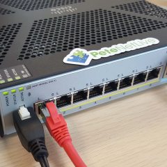
Cisco ASA: “Wrong Serial Number?”

KB ID 0001530

Problem

Cisco have done this for a while, the first time I saw it was years ago on a 5585, but all the NGFW models now have a ‘Serial Number” and a “Chassis Serial Number”. Normally you don’t care unless you need to log a TAC call online. So you issue a show version command, take a note of the serial number, and then it says, there’s no record of that serial number?

Solution

Just to be clear

SmartNets are registered to the Chassis Serial Number, this is NOT the serial number shown with a ‘show version‘ command.

Software (e.g. AnyConnect) is licensed to the Serial Number that IS shown with a ‘show version‘ command.

As a general rule, Cisco ASA chassis serial numbers start with JMX, and the serial numbers start with JAD.

How to Locate the Cisco ASA ‘Chassis Serial Number’

Well it’s printed on the chassis of course, but if it’s in a rack or a thousand miles away, that’s not much help! To get it remotely you use the ‘show inventory’ command;

[box]

Petes-ASA# show inventory
Name: "Chassis", DESCR: "ASA 5516-X with FirePOWER services, 8GE, AC, DES"
PID: ASA5516           , VID: V05     , SN: JMX1234ABCD

Name: "Storage Device 1", DESCR: "ASA 5516-X SSD"
PID: ASA5516-SSD       , VID: N/A     , SN: MSA21470XXX

Petes-ASA#

[/box]

How to Locate the Cisco ASA ‘Serial Number’

Same as with the old 5500 series firewalls, (and the PIX) use a show version command.

[box]

Petes-ASA# show version

Cisco Adaptive Security Appliance Software Version 9.8(2)24
Firepower Extensible Operating System Version 2.2(2.75)
Device Manager Version 7.8(2)151

Compiled on Thu 01-Mar-18 20:21 PST by builders
System image file is "disk0:/asa982-24-lfbff-k8.SPA"
Config file at boot was "startup-config"

Petes-ASA up 146 days 1 hour
failover cluster up 146 days 1 hour

Hardware:   ASA5516, 8192 MB RAM, CPU Atom C2000 series 2416 MHz, 1 CPU (8 cores)
Internal ATA Compact Flash, 8000MB
BIOS Flash M25P64 @ 0xfed01000, 16384KB

Encryption hardware device : Cisco ASA Crypto on-board accelerator (revision 0x1)
                             Number of accelerators: 1

 1: Ext: GigabitEthernet1/1  : address is 00a7.42e1.6ed6, irq 255
 2: Ext: GigabitEthernet1/2  : address is 00a7.42e1.6ed7, irq 255
 3: Ext: GigabitEthernet1/3  : address is 00a7.42e1.6ed8, irq 255
 4: Ext: GigabitEthernet1/4  : address is 00a7.42e1.6ed9, irq 255
 5: Ext: GigabitEthernet1/5  : address is 00a7.42e1.6eda, irq 255
 6: Ext: GigabitEthernet1/6  : address is 00a7.42e1.6edb, irq 255
 7: Ext: GigabitEthernet1/7  : address is 00a7.42e1.6edc, irq 255
 8: Ext: GigabitEthernet1/8  : address is 00a7.42e1.6edd, irq 255
 9: Int: Internal-Data1/1    : address is 00a7.42e1.6ed5, irq 255
10: Int: Internal-Data1/2    : address is 0000.0001.0002, irq 0
11: Int: Internal-Control1/1 : address is 0000.0001.0001, irq 0
12: Int: Internal-Data1/3    : address is 0000.0001.0003, irq 0
13: Ext: Management1/1       : address is 00a7.42e1.6ed5, irq 0
14: Int: Internal-Data1/4    : address is 0000.0100.0001, irq 0

Licensed features for this platform:
Maximum Physical Interfaces       : Unlimited      perpetual
Maximum VLANs                     : 150            perpetual
Inside Hosts                      : Unlimited      perpetual
Failover                          : Active/Active  perpetual
Encryption-DES                    : Enabled        perpetual
Encryption-3DES-AES               : Enabled        perpetual
Security Contexts                 : 2              perpetual
Carrier                           : Disabled       perpetual
AnyConnect Premium Peers          : 4              perpetual
AnyConnect Essentials             : Disabled       perpetual
Other VPN Peers                   : 300            perpetual
Total VPN Peers                   : 300            perpetual
AnyConnect for Mobile             : Disabled       perpetual
AnyConnect for Cisco VPN Phone    : Disabled       perpetual
Advanced Endpoint Assessment      : Disabled       perpetual
Shared License                    : Disabled       perpetual
Total TLS Proxy Sessions          : 1000           perpetual
Botnet Traffic Filter             : Disabled       perpetual
Cluster                           : Enabled        perpetual
Cluster Members                   : 2              perpetual
VPN Load Balancing                : Enabled        perpetual


Failover cluster licensed features for this platform:
Maximum Physical Interfaces       : Unlimited      perpetual
Maximum VLANs                     : 150            perpetual
Inside Hosts                      : Unlimited      perpetual
Failover                          : Active/Active  perpetual
Encryption-DES                    : Enabled        perpetual
Encryption-3DES-AES               : Enabled        perpetual
Security Contexts                 : 4              perpetual
Carrier                           : Disabled       perpetual
AnyConnect Premium Peers          : 8              perpetual
AnyConnect Essentials             : Disabled       perpetual
Other VPN Peers                   : 300            perpetual
Total VPN Peers                   : 300            perpetual
AnyConnect for Mobile             : Disabled       perpetual
AnyConnect for Cisco VPN Phone    : Disabled       perpetual
Advanced Endpoint Assessment      : Disabled       perpetual
Shared License                    : Disabled       perpetual
Total TLS Proxy Sessions          : 1000           perpetual
Botnet Traffic Filter             : Disabled       perpetual
Cluster                           : Enabled        perpetual
VPN Load Balancing                : Enabled        perpetual

The Running Activation Key feature: 2000 TLS Proxy sessions exceed the limit on the platform, reduced to 1000 TLS Proxy sessions.

Serial Number: JAD1234ABCD
Running Permanent Activation Key: 0x0037exxx 0x482ffyyy 0x04718yyy 0xaad48xxx 0x49343xxx
Configuration register is 0x1
Image type                : Release
Key Version               : A
Configuration last modified by PeteLong at 13:50:02.750 GMT Tue Mar 26 2019

Petes-ASA#

[/box]

Related Articles, References, Credits, or External Links

NA

Cisco Add FirePOWER Module to FirePOWER Management Center

KB ID 0001178 

Problem

If you only have one FirePOWER service module you can now manage it from the ASDM;

ASA 5505-X / 5508-X Setup FirePOWER Services (for ASDM)

But if you have got more than one, and you can manage them centrally with the FirePOWER Management Center, (formally SourceFIRE Defence Center). 

WARNING:  If you are going to use FMC DON’T register your licences in the ASDM, they all need to be registered in the FMC.


Solution

Before you can register the SFR module in the FMC, you need to have set it up, and have ran though the initial setup. The process is the same if you intend to use the ASDM or the FMC. You can then choose whether to register from command line in the SFR, or via the ASDM.

Register SFR with FMC via Command Line

Connect to the parent firewall and open a session with the sfr module;

[box]

PETES-ASA# session sfr
Opening console session with module sfr.
Connected to module sfr. Escape character sequence is 'CTRL-^X'.

PETES-SFR login: admin
Password:{pasword}
Last login: Fri Apr  8 05:04:49 UTC 2016 on ttyS1

Copyright 2004-2015, Cisco and/or its affiliates. All rights reserved.
Cisco is a registered trademark of Cisco Systems, Inc.
All other trademarks are property of their respective owners.

Cisco Fire Linux OS v6.0.0 (build 258)
Cisco ASA5506 v6.0.0 (build 1005)

> 

[/box]

You can then add the FMC as a manager, you will need to supply a registration key.

[box]

> configure manager add 10.9.20.25 password123
Manager successfully configured.
Please make note of reg_key as this will be required while adding Device in FMC.

[/box]

Register SFR with FMC via ASDM

Connect to the ASDM > Configuration > ASA FirePOWER Configuration > Integration  >Remote Management > Add Manager.

Specify the IP of the FMC Appliance, and registration key > Save.

It should then say ‘pending registration’.

Configure the FirePOWER Management Appliance to Accept the SFR Registration 

Log into FMC > Devices > Device Management > Add Device.

Provide the IP of the SFR module, a display name, the registration key you used above. If you have setup a group you can use it and select your Access Control Policy (dont panic if you have not configured one yet) > Register.

It can take a while, but eventually it should register like so;

Problems

Could not establish a connection with sensor. Make sure the registration keys match, that the software versions are compatible,and that the network is not blocking the connection.

Had this problem for a while, (Credit to Craig Paolozzi for finding the fix.) Both the SFR, and the FMC console needed static routes adding to them (even though they could ping each other!) Pointing to each other.

Related Articles, References, Credits, or External Links

NA

Event ID 1026

KB ID 0000134 

Problem

Event ID 1026

The DNS server was unable to create a name in memory for name “<host name>” in zone “<zone name>” in the Active Directory. This directory name is ignored. Use the DNS console to recreate the records associated with this name or check that the Active Directory is functioning properly and reload the zone. The event data contains the error. 

DNS cant be updated with the name of something thats trying to add itself to DNS.

Solution

  1. This is due to DNS nodes that have characters in them windows does not like (e.g. ! ‘ etc) you can delete them in the following way
  2. Start > run > dsa.msc
  3. View > Advanced Features
  4. Domain name > System > Microsoft DNS
  5. Note any records for reverse DNS zones that longer exist should be removed from here at this point
  6. Then locate then offending entries (they will have a type of ‘dnsnode’) and delete them.

However if you have machines on the network that are going to “re-register” themselves (e.g Apple Mac’s Firewalls and routers – then the problem will reoccur)

If the problem does reoccurs then you need to go to the DNS server and ALLOW names it does not allow by default (note this is not recommended by Microsoft) If you want to do this.


      • On the DNS server Start > Administrative tools > DNS
      • Right click the server name > properties > Advanced
      • Change the Name Checking section to “All Names”
      • Restart the DNS Server service (or right click the Server name > All tasks > Restart


Related Articles, References, Credits, or External Links

NA

Windows – Error ‘A Good Time server could not be located’

KB ID 0000705

Problem

Seen when running dcdiag,

Error(s):

Starting test: Advertising
Warning: Server-Name is not advertising as a time server.
......................... Server-Name failed test Advertising


Running enterprise tests on : PeteNetLive.com Starting test: Intersite ……………………. PeteNetLive.com passed test Intersite Starting test: FsmoCheck Warning: DcGetDcName(TIME_SERVER) call failed, error 1355 A Time Server could not be located. The server holding the PDC role is down. Warning: DcGetDcName(GOOD_TIME_SERVER_PREFERRED) call failed, error 1355 A Good Time Server could not be located. ……………………. PeteNetLive.com failed test FsmoCheck

Solution

Note: Any one of the things below can cause this problem, I suggest you retry running dcdiag after each step until it runs without error.

1. In a windows domain, clients normally get their time from the domain controller that holds the PDC Emulator role. Locate that server and log on.

Locate your FSMO Role Servers

2. Now configure your PDC emulator to get its time from a reliable external source.

Windows – Setting Domain Time

3. If you have got this far, then should already have the windows time service running, check!

4. From command line, remove and reinstall the Windows time service with the following two commands.

[box]w32tm /unregister<br />w32tm /register[/box]

Note: It’s not unusual to see the following error after you issue a ‘w32tm /unregister’ command,

Error
The following error occurred: Access is denied (0x80070005)

If this happens don’t panic, open the services console (Press F5) and the Windows Time Service may have disappeared (if so re-register it). If not manually stop the Windows Time service and try to unregister again, then re-register.

WARNING: After doing this, you will need to set the time service to get reliable time from an NTP External Server again.

5. Press Windows Key+R > regedit {enter} > Navigate to the following registry key;

[box]HKLM > System > CurrentControlSet > services > W32Time > Parameters[/box]

Ensure the Type value it set to NTP, the restart the Windows time service and check again.

5. Whilst still in the registry editor navigate to;

[box]HKLM > System > CurrentControlSet > services > W32Time > Config[/box]
Set the AnnounceFlags value to 5.

6. Whilst still in the registry editor navigate to;

[box]HKLM > System > CurrentControlSet > services > W32Time > Time Providers > NtpServer[/box]

Make sure the Enabled value is set to 1 (one).

7. If the problem persists, on the PDC Emulator run gpedit.msc > Navigate to;

[box]Computer Configuration > Administrative Templates > system > Windows Time Service[/box]

Make sure ‘Global Configuration Settings’ is set to ‘Not Configured’.

Navigate to;

[box]Computer Configuration > Administrative Templates > system > Windows Time Service > Time Providers[/box]

Make ALL the settings are to ‘Not Configured’.

If you changed anything, run ‘gpupdate /force’ and try again.

8. On the PDC Emulator, Open a command window (Note: You must Run as Administrator!) > In the Computer Settings section locate all the policies that are applying to the server.

Note: As a shortcut to find the offending policy, you could run ‘gpresult /v > c:gpresult.txt’ then search that text file, for any instance of w32tm, (here’s an example).

As above navigate to;

[box]Computer Configuration > Administrative Templates > system > Windows Time Service[/box]

Make sure Global Configuration Settings is set to ‘Not Configured’.

Navigate to;

[box]Computer Configuration > Administrative Templates > system > Windows Time Service > Time Providers[/box]

Make ALL the settings are set to ‘Not Configured’.

If you changed anything, run ‘gpupdate /force’ and try again.

Related Articles, References, Credits, or External Links

NA

Register HP Wireless Access Points With an HP MSM Controller on a Different Subnet

KB ID 0000913 

Problem

If you have HP Access Points on remote sites, you have the choice of either leaving them in automomous mode, or registering them with a controller at another site. This is handy if you want to manage all your VSC’s from one location. You can do this via DNS, or via DHCP at that remote site, (I tend to setup both to be on the safe side).

Solution

Option 1: Set MSM Controller Location via DHCP

1. On your DHCP server, open the DHCP management console.

2. Expand the IPv4 scopes.

3. Action > Define Vendor Class.

4. Add >Display name = Colubris > Description = Vendor Class for Colubris Products > Under ASCII Set the value to Colubris-AP > The rest of the values will autofill > OK > Close.

5. Right click IPv4 > Set Predefined Options.

6. Set the Option class to Colubris > Add > Name = MSC > Data type = IP Address > Array = Ticked > Description = List of MSC IP Addressses > OK > OK.

7. Locate you active DHCP scope, and expand it > Right click > Configure Options.

8. Advanced Tab > Vendor Class = Colubris > 001 MSC = Tick > IP Address > Set the IP address(s) of your controller(s) > Apply > OK.

9. Check you can see the option listed, (as below).

Option 2: Set MSM Controller Location via DNS

1. In the forward lookup zone for your domain, you can create A/Host records for your MSM controller(s). Create them in the cnsrv1, cnsrv2, etc format.

WARNING:

You may find that you have a problem with the Access Points flagged as ‘Waiting Acceptance‘, if that happens see the following link.

HP MSM Controller – Access Points Stuck ‘Waiting Acceptance’

Related Articles, References, Credits, or External Links

Manually Configuring HP Wireless (MSM 720 controller) for Public and Private Wireless Networks


Implementing GDOI into DMVPN

KB ID 0000956 

Problem

Just recently I covered DMVPN, which is a great scalable system for adding new sites to your network infrastructure and have them join an existing VPN solution without the need to add extra config at the ‘hub’ site.

One of the advantages of DMVPN is it maintains VPN connections from your ‘Spoke’ sites back to the ‘Hub’ site, but if a spoke site needs to speak to another spoke site, it will dynamically build a VPN tunnel to that spoke site.

That’s great right? Well it’s pretty cool, but there is a downside. There is a slight ‘lag’ while that dynamic VPN is established, for normal network traffic you probably wont even notice, but if you are sending streaming media, or voice traffic then it becomes more of a problem.

So if we had a system where all the routers have all the same settings, the hub router wouldn’t need to ‘broker’ the initial connection and the routers get all their VPN settings from a central ‘Server’. Well that’s what GDOI gives us, we set up a router as a central ‘Key Server’ and all the other GDOI ‘Group Members’ register with the key server, and get all their settings.

So I’ll use the same network that I built the DMVPN on, I’ve added another router that will be the ‘Key Server’, other than that the topology is the same.

Note: The GDOI Key Server, cannot run on the DMVPN hub router.

Solution

GDOI Key Server Setup

1. Firstly setup the requirements for ISAKMP phase 1. Note: here I’m using pre-shared keys, this does not scale well if you have a lot of sites, you might want to look at a PKI solution and use certificates instead.

[box]

crypto isakmp policy 10
encr aes
authentication pre-share
group 2
crypto isakmp key P@ssword123 address 0.0.0.0 0.0.0.0

EXAMPLE

KS#configure terminal
Enter configuration commands, one per line. End with CNTL/Z.
KS(config)#crypto isakmp policy 10
KS(config-isakmp)#encr aes
KS(config-isakmp)#authentication pre-share
KS(config-isakmp)#group 2
KS(config-isakmp)#crypto isakmp key P@ssword123 address 0.0.0.0 0.0.0.0
KS(config)#

[/box]

2. Then setup IPSEC phase 2 requirements. With a transform-set and a profile.

[box]

crypto ipsec transform-set TS-GDOI esp-aes esp-sha-hmac

crypto ipsec profile PF-GDOI
set transform-set TS-GDOI

EXAMPLE

KS(config)#crypto ipsec transform-set TS-GDOI esp-aes esp-sha-hmac
KS(cfg-crypto-trans)#crypto ipsec profile PF-GDOI
KS(ipsec-profile)#set transform-set TS-GDOI
KS(ipsec-profile)#

[/box]

3. The Key server will use its certificate for authentication, if you DO have a PKI solution and this router has already enrolled to it then you can skip this step. If not you need to generate a LOCAL certificate on the key server. (Note: This requires the device to have a hostname and domain name set).

[box]

ip domain-name testbench.local
crypto key generate rsa modulus 2048

EXAMPLE

KS(config)#ip domain-name testbench.local
KS(config)#crypto key generate rsa modulus 2048

% The key modulus size is 2048 bits
% Generating 2048 bit RSA keys, keys will be non-exportable...
*Mar 1 00:17:13.591: %SSH-5-ENABLED: SSH 1.99 has been enabled
KS(config)#

[/box]

4. To setup the key server, create a group (GDOI-VPN) and give it an identity number,all members of the group will share this number. It used the profile we created above, and will apply encryption based on ACL 123 (we will create in a minute). Finally it sets the IP that it will be used as the key servers (this is the IP in use on FastEthernet 0/0).

[box]

crypto gdoi group GDOI-DMVPN
identity number 999
server local
rekey retransmit 10 number 2
rekey authentication mypubkey rsa rsa
rekey transport unicast
sa ipsec 10
profile PF-GDOI
match address ipv4 123
replay counter window-size 64
address ipv4 5.5.5.2

EXAMPLE

KS(config)#crypto gdoi group GDOI-DMVPN
KS(config-gdoi-group)#identity number 999
KS(config-gdoi-group)#server local
KS(gdoi-local-server)# rekey retransmit 10 number 2
KS(gdoi-local-server)# rekey authentication mypubkey rsa rsa
KS(gdoi-local-server)# rekey transport unicast
KS(gdoi-local-server)# sa ipsec 10
KS(gdoi-sa-ipsec)# profile PF-GDOI
KS(gdoi-sa-ipsec)# match address ipv4 123
KS(gdoi-sa-ipsec)# replay counter window-size 64
KS(gdoi-sa-ipsec)# address ipv4 5.5.5.2
KS(gdoi-local-server)#

[/box]

5. Create the ACL we specified above, this ACL will get downloaded to all the group members. As will the VPN profile, they will then apply that profile to traffic defined in the ACL. It’s an ‘interesting traffic ACL, (if you are used to working with VPN’s).

[box]

access-list 123 permit gre any any

EXAMPLE

KS(config)#access-list 123 permit gre any any
KS(config)#

[/box]

Setup GDOI Group Members

Note: These settings are the same for the DMVPN hub router and all the spoke routers.

6. As above we specify a matching phase 1 policy.

[box]

crypto isakmp policy 10
encr aes
authentication pre-share
group 2
crypto isakmp key P@ssword123 address 0.0.0.0 0.0.0.0

EXAMPLE

Branch1#configure terminal
Enter configuration commands, one per line. End with CNTL/Z.
Branch1(config)#crypto isakmp policy 10
Branch1(config-isakmp)#encr aes
Branch1(config-isakmp)#authentication pre-share
Branch1(config-isakmp)#group 2
Branch1(config-isakmp)#crypto isakmp key P@ssword123 address 0.0.0.0 0.0.0.0
Branch1(config)#

[/box]

7. Then join the router to the GDOI group.

[box]

crypto gdoi group GDOI-DMVPN
identity number 999
server address ipv4 5.5.5.2

EXAMPLE

Branch1(config)#crypto gdoi group GDOI-DMVPN
Branch1(config-gdoi-group)#identity number 999
Branch1(config-gdoi-group)#server address ipv4 5.5.5.2
Branch1(config-gdoi-group)#exit

[/box]

8. Then use that group to create a ‘crypto map’, and apply that map to the public interface that ‘faces outwards’. Note: Normally when applying encryption to DMVPN you would apply your crypto to the tunnel interface, with GDOI you do NOT.

[box]

crypto map CM-GDOI 10 gdoi
set group GDOI-DMVPN
interface FastEthernet0/0
crypto map CM-GDOI

EXAMPLE

Branch1(config)#crypto map CM-GDOI 10 gdoi
% NOTE: This new crypto map will remain disabled until a valid
group has been configured.
Branch1(config-crypto-map)#set group GDOI-DMVPN
Branch1(config-crypto-map)#interface FastEthernet0/0
Branch1(config-if)#crypto map CM-GDOI
*Mar 1 05:11:31.546: %CRYPTO-5-GM_REGSTER: Start registration to KS 5.5.5.2 for group GDOI-DMVPN using address 2.2.2.1
*Mar 1 05:11:31.582: %CRYPTO-6-GDOI_ON_OFF: GDOI is ON

[/box]

9. Now I could add a route to my DMVPN network, with a static statement (i.e. ip route 192.168.0.0 0.0.255.255 Tunnel0), but I’m using EIGRP anyway, so I can just advertise the DMVPN network into my EIGRP group.

[box]

router eigrp 20
network 192.168.0.0

EXAMPLE

Branch1(config)#router eigrp 20
Branch1(config-router)#network 192.168.0.0
Branch1(config-router)#exit
Branch1(config)#

[/box]

Testing GDOI

[box]

Branch1#show crypto session
Crypto session current status

Interface: FastEthernet0/0
Session status: UP-ACTIVE
Peer: port 848
IKE SA: local 2.2.2.1/848 remote 5.5.5.2/848 Active
IPSEC FLOW: permit 47 0.0.0.0/0.0.0.0 0.0.0.0/0.0.0.0
Active SAs: 2, origin: crypto map

Branch1#

Branch1#show crypto gdoi
GROUP INFORMATION

    Group Name               : GDOI-DMVPN
    Group Identity           : 999
    Rekeys received          : 0
    IPSec SA Direction       : Both
    Active Group Server      : 5.5.5.2
    Group Server list        : 5.5.5.2

    GM Reregisters in        : 2042 secs
    Rekey Received           : never


    Rekeys received
         Cumulative          : 0
         After registration  : 0

 ACL Downloaded From KS 5.5.5.2:
   access-list  permit gre any any

TEK POLICY for the current KS-Policy ACEs Downloaded:
  FastEthernet0/0:
    IPsec SA:
        spi: 0x93842CD3(2474912979)
        transform: esp-aes esp-sha-hmac
        sa timing:remaining key lifetime (sec): (2197)
        Anti-Replay : Disabled

[/box]

Complete GDOI with DMVPN Configs

Below I’ll show the configs, with the GDOI config highlighted in Red and the DMVPN config highlighted in blue.

[box]

GDOI Key Server Config

version 12.4
service timestamps debug datetime msec
service timestamps log datetime msec
no service password-encryption
!
hostname KS
!
boot-start-marker
boot-end-marker
!
no aaa new-model
memory-size iomem 5
no ip icmp rate-limit unreachable
ip cef
!
no ip domain lookup
!
multilink bundle-name authenticated
!
archive
log config
hidekeys
!
crypto isakmp policy 10
encr aes
authentication pre-share
group 2
crypto isakmp key P@ssword123 address 0.0.0.0 0.0.0.0
!
crypto ipsec transform-set TS-GDOI esp-aes esp-sha-hmac 
!
crypto ipsec profile PF-GDOI
set transform-set TS-GDOI
!
crypto gdoi group GDOI-DMVPN
identity number 999
server local
rekey retransmit 10 number 2
rekey authentication mypubkey rsa rsa
rekey transport unicast
sa ipsec 10
profile PF-GDOI
match address ipv4 123
replay counter window-size 64
address ipv4 5.5.5.2
!
ip tcp synwait-time 5
!
interface FastEthernet0/0
ip address 5.5.5.2 255.255.255.252
speed auto
half-duplex
!
interface FastEthernet0/1
no ip address
shutdown
duplex auto
speed auto
!
router eigrp 20
network 5.5.5.0 0.0.0.3
no auto-summary
!
ip forward-protocol nd
!
no ip http server
no ip http secure-server
!
access-list 123 permit gre any any
!
control-plane
!
line con 0
exec-timeout 0 0
privilege level 15
logging synchronous
line aux 0
exec-timeout 0 0
privilege level 15
logging synchronous
line vty 0 4
login
!
end

[/box]

DMVPN Hub Server Config

[box]


version 12.4 
service timestamps debug datetime msec 
service timestamps log datetime msec 
no service password-encryption 
! 
hostname MainSiteRTR
! 
boot-start-marker 
boot-end-marker 
! 
no aaa new-model 
memory-size iomem 5 
no ip icmp rate-limit unreachable 
ip cef ! no ip domain lookup 
! 
multilink bundle-name authenticated 
! 
archive 
log config 
hidekeys 
! 
crypto isakmp policy 10 
encr aes 
authentication pre-share 
group 2 
crypto isakmp key P@ssword123 address 0.0.0.0 0.0.0.0
 
!
crypto gdoi group GDOI-DMVPN 
identity number 999 
server address ipv4 5.5.5.2 
!
crypto map CM-GDOI 10 gdoi 
set group GDOI-DMVPN 
! 
ip tcp synwait-time 5 
!
interface Tunnel0 
ip address 192.168.0.1 255.255.255.0 
no ip redirects 
ip nhrp map multicast dynamic 
ip nhrp network-id 1 tunnel source 1.1.1.1 
tunnel mode gre multipoint 
! 
interface FastEthernet0/0 
ip address 172.16.1.1 255.255.0.0 
duplex auto 
speed auto 
! 
interface FastEthernet0/1 
ip address 1.1.1.1 255.255.255.252 
duplex auto 
speed auto 
crypto map CM-GDOI 
! 
interface FastEthernet1/0 
ip address 5.5.5.1 255.255.255.252 
duplex auto 
speed auto 
! 
router eigrp 20 
network 1.1.1.0 0.0.0.3 
network 5.5.5.0 0.0.0.3 
network 172.16.1.0 0.0.0.255 
network 192.168.0.0 
no auto-summary 
! 
ip forward-protocol nd 
ip route 0.0.0.0 0.0.0.0 FastEthernet0/1 
! 
no ip http server 
no ip http secure-server 
! 
no cdp log mismatch duplex 
! 
control-plane 
! 
line con 0 
exec-timeout 0 0 
privilege level 15 
logging synchronous 
line aux 0 
exec-timeout 0 0 
privilege level 15 
logging synchronous 
line vty 0 4 
login 
! 
end 

Branch (Spoke) Routers 

version 12.4 
service timestamps debug datetime msec 
service timestamps log datetime msec 
no service password-encryption 
! 
hostname Branch1 
! 
boot-start-marker 
boot-end-marker 
! 
no aaa new-model
memory-size iomem 5 
no ip icmp rate-limit unreachable 
ip cef 
! 
no ip domain lookup 
! 
multilink bundle-name authenticated 
! 
archive log 
config hidekeys 
! 
 crypto isakmp policy 10 
encr aes 
authentication pre-share 
group 2 
crypto isakmp key P@ssword123 address 0.0.0.0 0.0.0.0 
!
 crypto gdoi group GDOI-DMVPN 
identity number 999 
server address ipv4 5.5.5.2 
!
 crypto map CM-GDOI 10 gdoi 
set group GDOI-DMVPN 
! 
ip tcp synwait-time 5 
!
 interface Tunnel0 ip address 192.168.0.2 255.255.255.0 
no ip redirects 
ip nhrp map 192.168.0.1 1.1.1.1 
ip nhrp map multicast 1.1.1.1 
ip nhrp network-id 1 
ip nhrp nhs 192.168.0.1 tunnel source 2.2.2.1 
tunnel mode gre multipoint 
! 
interface FastEthernet0/0 
ip address 2.2.2.1 255.255.255.252 
duplex auto 
speed auto 
crypto map CM-GDOI 
! 
interface FastEthernet0/1
ip address 172.17.1.1 255.255.0.0
duplex auto 
speed auto 
! 
router eigrp 20 
network 2.2.2.0 0.0.0.3 
network 172.17.0.0 
network 192.168.0.0
 no auto-summary 
! 
ip forward-protocol nd 
ip route 0.0.0.0 0.0.0.0 FastEthernet0/0 
! 
no ip http server 
no ip http secure-server 
! 
control-plane
! 
line con 0 
exec-timeout 0 0 
privilege level 15 
logging synchronous 
line aux 0 
exec-timeout 0 0 
privilege level 15 
logging synchronous 
line vty 0 4 
login 
! 
end

[/box]

Related Articles, References, Credits, or External Links

Cisco – Configuring Dynamic Multipoint Virtual Private Networks DMVPN

Using OSPF over DMVPN

Cisco ASA 5500 – Install and Configure a CSC Module

KB ID 0000731 

Problem

The Cisco CSC module provides ‘in line’ scanning of POP3, SMTP, HTTP and FTP traffic, to protect against viruses but also for anti spam and anti phish (with the correct licensing).

If you are familiar with Trend products, you will like it, (because that’s what it runs), and the interface is much the same as Trend IWSS.

It is a hardware device that plugs into the back of the ASA, and comes in two flavours.

1. CSC-SSM-10 (50 to 500 users, depending on licenses) for ASA 5510 and 5520.

2. CSC-SSM-20 (500 to 100 users, depending on licenses) for ASA 5510, 5520, and 5540.

In addition to licensing the amount of users, you can also buy a Plus License, this enables anti-spam, anti-phish, URL filtering, and blocking control. Note: This license expires and must be renewed annually).

Solution

Some licenses on the CSC are time specific, I would consider setting the ASA’s internal clock before you start.

Set the ASA to get time from an External NTP Server

Step 1: License the Cisco CSC Module

1. Connect to the ASA via command line, go to enable mode and issue the following command;


From the output you should be able to get the serial number of the CSC module (write it down).

2. In the box with the CSC/ASA should be an envelope containing the PAK for the CSC module, write that number down as well.

3. Go to the Cisco license portal here, Note: If you do not have a Cisco CCO account you may need to create one. Enter your PAK code > Fulfill Single PAK.

Note: If you have multiple PAK codes, you can do them at once with the ‘Load more PAK’s’ button, this may be the case if you also have a ‘plus’ license to add.

4. Enter the serial number of your CSC module and the person/company from whom you bought it > Next.

5. It should display your valid email address (from your CCO account). Tick the box to accept the terms and conditions > Get License.

6. Scroll down and accept, then select DOWNLOAD, (that way you wont have to wait for it to be emailed to you).

7. Open the license file (will have a .lic extension) with notepad and you should see two keys.

Step 2: Setup the CSC Module

Note: Here I’m going to simply set up inspection of everything on all interfaces, this might not be what you want, i.e. if theres no mail server in the DMZ why would you want to inspect all DMZ traffic for SMTP.

1. Connect to the firewall’s ASDM console > Trend Micro Content Security > It should point you straight to the setup wizard.

9. Enter the base and plus license codes. Note: The plus license code that comes with the CSC is just an evaluation one, if you have purchased a plus license separately, then paste THAT code in instead.

10. Enter the network settings you require for the CSC (it requires its own network connection). it has a single RJ45 network socket on the CSC modules back plane, connect that to your LAN > Next.

11. Supply a name for the CSC module and details of your email server (if you require email notification) > Next > enter the IP addresses that will be allowed access to the CSC web console > Next > Change the password Note: The original password will be cisco > Next.

12. Select what traffic you want to inspect, here I’ve selected all traffic all interfaces > Ive set the CSC to fail open (if theres a problem it simply passes traffic, if you have it on fail close and the CSC encounters a problem all http, smtp, ftp, and pop traffic will be blocked until the problem is resolved) > OK > Next.

13. Review the settings > Finish.

Note: You may get a warning if you set ‘fail open’ above that’s OK.

Connecting to and Managing the Cisco CSC Module

Although you can access the CSC settings via the ASDM, the easiest way is via its web interface, you set the IP address in step 2 number 10 above, navigate to
https://{ip-address}:8443

Note: You should now set the CSC module so that is DOES NOT scan its own update traffic, see the following article.

Cisco CSC Module – Stop it scanning its own update traffic

Adding a ‘PLUS’ License to a Cisco CSC

If you add the plus license later, you will obtain the code in the same manner as you did above (put the PAK and the CSC Serial number into the licensing portal and have it sent to you.

1. Once you have the code, open a web session to the CSC management interface https://{ip-address}:8443 > Administration > Licensing > Enter a new code.

2. Paste in the new code > Activate.

3. It may look like it has hung, wait a minuter or so, and check the licensing tab again.

Related Articles, References, Credits, or External Links

Cisco CSC Module Error – Activation Warning

Apple Devices will not Update Though Cisco ASA and CSC Module

Outlook Error 0x800CCC0F – Using POP3 To Exchange – Behind a Cisco CSC (Trend InterScan) Module