
KB ID 0001495
Problem
I was recently involved in deploying an HPe Synergy 12000 Frame. And the network connections from it were ‘a little unusual’ so I thought I’d document that here, to save anyone else the problems I had.
I was connecting to an HP/Aruba 5412 switch so my cables were all HP/Aruba (to be on the safe side).

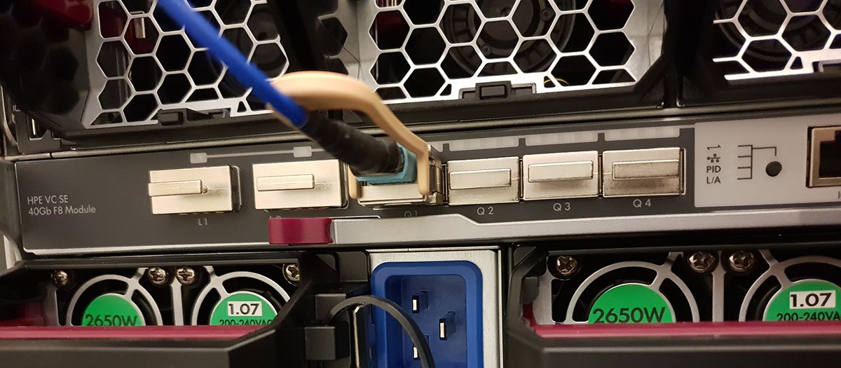
What you can see (above) is the MPIO Cable (K2Q46A P/N 800867-001) fixed onto the left (and above boxed,) there is a QSFP (P/N 817040-B21.) Note: this can be used either as 4 x 10Gbe or 4 x 8GbFC). On the right you can see the cable ends in 4x Standard LC fibre connectors, so you will also need 4x 10GB SR SFP+ Modules (Aruba P/N J1950D) – shown bottom right.
So what does it do? (Apart from cost a fortune!) Well the QSFP connects at 40Gb and splits the traffic down into 4 x 10Gb
Cabling and Configuring MPIO QSFP
Connecting up is pretty straight forward, REMEMBER when you connect the 40GB QSFP to the Synergy it will light purple if its connected, and flash purple when it sees activity.
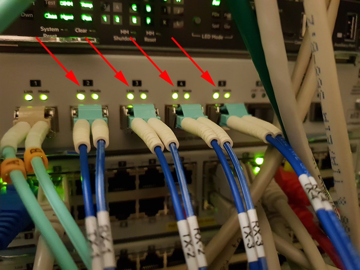
Connecting to the switch is also easy enough, (WARNING: All the ports need to be Trunked (HP) or Ether Channelled (Cisco,)) with LACP enabled. You don’t need to worry about configuring LACP on the Synergy, that’s handled automatically by the ‘Uplink set’.
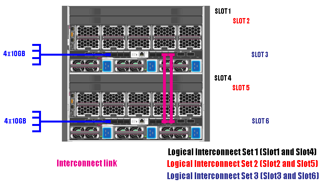
So the back of the ‘Frame’ has two interconnect links (If you are from a switch background think of these like stacking cables). And two MPIO uplink cables.
HPe/Aruba Switch Config For MPIO
As previously stated, the switch I’m using is an Aruba 5412, with two 8 Port 1Gb/10Gb modules (J9993-A). Here’s the relevant switch config;
Firstly give the interfaces a sensible name;
!
interface A2
   name "Trunk Link to Synergy VC1 Port Q1"
   exit
interface A3
   name "Trunk Link to Synergy VC1 Port Q1"
   exit
interface A4
   name "Trunk Link to Synergy VC1 Port Q1"
   exit
interface A5
   name "Trunk Link to Synergy VC1 Port Q1"
   exit
!
interface B2
   name "Trunk Link to Synergy VC2 Port Q1"
   exit
interface B3
   name "Trunk Link to Synergy VC2 Port Q1"
   exit
interface B4
   name "Trunk Link to Synergy VC2 Port Q1"
   exit
interface B5
   name "Trunk Link to Synergy VC2 Port Q1"
   exit
!

Show any 'already configured' Trunk links with a 'show trunk' command
In my case two existed, (Trk1 and Trk2). So I used Trk3;

!
trunk A2-A5,B2-B5 Trk3 LACP
!

Now UNTAG vlan 1 (assuming that's your default VLAN) And TAG and VLANS that
need to be used in the Synergy Deployment. (Note on an HP switch simply add
the Trk3 to the existing settings like so;

!
vlan1
untagged A6-A8,B6-B8,E1-E24,F1-F24,G3-G12,H3-H12,Trk1-Trk3
!
vlan 100
   tagged Trk1-Trk3
   exit
vlan 101
   tagged Trk1-Trk3
   exit
vlan 102
   tagged Trk1-Trk3
   exit
vlan 103
   tagged Trk1-Trk3
   exit
etc.
Cisco Switch Config For MPIO
If you have a Cisco Switch then instead of ‘Trunking’ you will be ‘Ether Channelling’ for a more detailed explanation see the following post
HP and Cisco – VLANs and Trunks Confusion!
!
interface port-channel 1
switchport trunk encapsulation dot1q
switchport mode trunk
!
interface range Te1/1 - 4 , Te2/1 - 4
switchport trunk encapsulation dot1q
switchport mode trunk
channel-protocol lacp
channel-group 1 mode active
!
Configuring Synergy 12000 Networking
The process is, you add Networks, then collect Networks together in Network Sets, Then you create Logical Interconnect Groups. Part of creating a Logical Interconnect Groups, involves creating an Uplink Set, which consists of both your Networks, and the The Uplink ports.
Note: A Network Set is used by a Server Profile, (or a Server Profile Template).
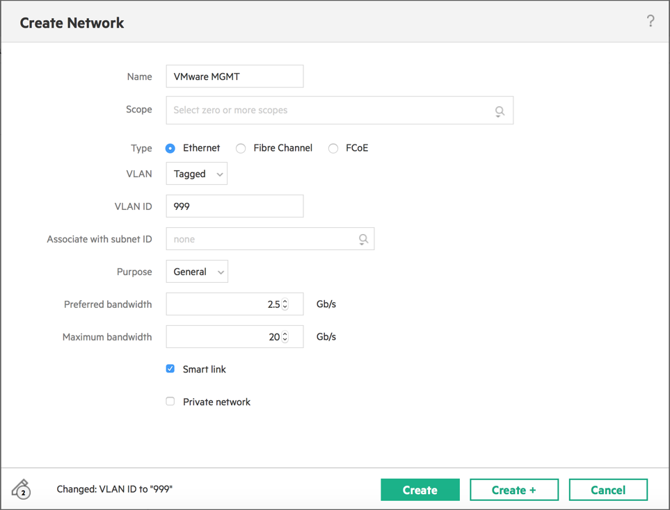
Create Networks
One View > Networking > Networks > Create Network
Create Network Sets
One View > Networking > Networks Sets > Create Network Set > Give it a name > Add Networks > Create.

Create Logical Interconnect Group
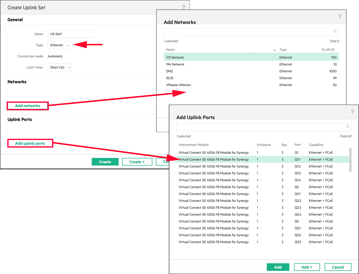
One View > Networking > Logical Interconnect Group > Create Logical Interconnect Group > Give it a name > Select the correct Interconnect Bay Set (see diagram above) > Select Interconnects > Add Uplink Set.

Give the set a name > Select the Type > Add in the Networks > Add in the Uplinks > Create.
Note: You only need to add in ALL the LOGICAL interfaces i.e. Q1:1, Q1:2,Q1:3,Q1:4 for EACH Interconnect module. .
After a few minutes if you look under One View > Networking > Logical Interconnects > You will see one listed that has the name of your Logical Interconnect group (with a divide symbol on the end!) Make sure ALL the logical uplinks are connected. (If not you will see LACP errors on the switch).

Related Articles, References, Credits, or External Links
NA