Cisco Firepower 1010 (FTD) Initial Setup

KB ID 0001678


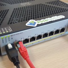
If you’re here you’ve either purchased a new Cisco Firepower device running FTD (FirePower Threat Defence) or have re-imaged your Firepower device from ASA to FTD code.

On its factory defaults, the unit will have the following settings.

  • Inside IP address (VLAN 1) 192.168.1.1 (on all interfaces from 2 to 8).
  • Outside IP Address set to DHCP in interface 1.
  • Management IP address 192.168.45.1 on the Management Interface.
  • DHCP Scopes on both the inside and management interfaces (192.168.1.x and 192.168.45.x respectively).

  1. Power Connector.
  2. 8 x Gigabit Ethernet ports: Normally GigabitEthernet 1/1 will be for the WAN, GigabitEthernet 1/2 though 1/8 will be for the LAN (with 1/7 and 1/8 being PoE).
  3. Management Port.
  4. Console Port (RJ45).
  5. Console Port (Mini USB).
  6. USB Port (useful for upgrades, and backups).
  7. Kensington Lock: Seriously? I’ve not seen one of these since about 2005, does anyone still use them?
  8. Reset Button: Depress for 3 seconds reverts the firewall to its factory settings, (and preserves the config apparently).
  9. Status Lights, (another reason not to put things on top of it!) Though you will notice there’s some on the back also. Note: When all lights are solid the firewall is operational, when the centre light is blinking, it’s still booting).

FirePower 1010 Setup

I will be deploying this as a stand alone FTD firewall, that will be managed locally on the device itself via FDM (Firepower Device Manager) and not via an FMC (Firepower Management Center) appliance.

Smart Licensing: If you’re not already familiar with Cisco Smart Licensing, I’ve covered it in more depth here. Set yourself up a free Smart License Account, and generate a token, copy it to the clipboard, (we will need it in a minute).

Connect to the firewall via a LAN port on https://192.168.1.1, or via the Management port on https://192.168.45.1 (unless you have ran though the FTD setup at command line, and have already changed the management IP).

Default usernames, (you will be asked to change them) are;

  • Username: admin
  • Password: Admin 123

Scroll down.

Here I’m accepting the default Outside/Public Interface settings of DHCP enabled, with IPv6 disabled, if yours has a static IP, or you want to user IPv6 then change the settings accordingly > Next.

I’ll accept the defaults here, be advised those NTP servers may take a little while to ‘go-green’ (you will see what I mean later) > Next.

I’m going to do this manually in a minute, so we can skip this > Next.

Note: The unit will have a default policy of let everything out (sourced from inside), and nothing in (sourced from outside) we will leave that as it is, as a decent start point.

Stanalone device > Configure Interfaces.

Note: Below I’m going to REMOVE the DHCP Scope, then change the ‘inside’ IP address (to avoid errors). Then later I will add the new DHCP scope back in again.

VLANs > Vlan1 > Edit. > DHCP section > Edit > Remove.

You can now set the inside IP address accordingly. (Don’t panic you wont lose connectivity yet!) > OK.

Now you need to Save/Commit the changes, and Deploy them. Now you will lose connectivity, if you have changed the inside IP address, so manually give yourself an IP address on the new network, and reconnect to the firewall.

Note: Update: Pleas ensure tha management is allowed in VLAN1 before proceeding (System Settings -> Management Access -> Data Interfaces.)

Cisco Firepower Setup DHCP

Create a new DHCP Scope: Should you require the firewall to be a DHCP server, log back in to the new internal IP address > System Settings > DHCP Server.

Create DHCP Server > Enable DHCP Server > Enter the new scope > OK.

Remember to commit the changes, and deploy them again!

Cisco Firepower FTD Licensing

Thankfully this is MUCH easier than doing the same thing while running ASA Code (on the same hardware!) > Smart Licence > View Configuration.

Register Device.

Paste in your token, (from above) > Set your location > Register Device. Go and have a coffee, it will look like it’s broken/not worked for a few minutes.

After a while you should see this;

There will be some outstanding changes to save and deploy also, now the unit is registered.

Back in the Cisco Smart Licence portal, it should look a bit like this;

Once fully complete and operational, all connected interfaces should have all the options ‘go-green’. For me the NTP servers took a while!

Note: Obviously the interfaces in orange are not in use!


Related Articles, References, Credits, or External Links

NA

ASA Setup FirePOWER Services (for ASDM)

KB ID 0001107 

Problem

Both the 5506-X (rugged version and wireless), and 5508-X now come with a FirePOWER services module inside them. This can be managed from either ASDM* (with OS and ASDM upgraded to the latest version), and via the FireSIGHT management software/appliance.

Related Articles, References, Credits, or External Links

*UPDATE: All ASA ‘Next-Gen’ firewalls can now have their Firepower Service Module managed from the ASDM.

Solution

1. The first thing to do is cable the management interface and the interface you are going to use as the ‘inside’ (LAN) into the same network (VLAN).

2. The next step might seem strange if you are used to working with Cisco firewalls, but you need to make sure there is no IP address configured on the management interface. Try to think of it as just the hole that the FirePOWER services module (which will get its own IP) speaks out though.

[box]

Petes-ASA# configure terminal
Petes-ASA(config)# interface Management1/1
Petes-ASA(config-if)# no nameif
WARNING: DHCPD bindings cleared on interface 'management', address pool removed
Petes-ASA(config-if)# no security-level
Petes-ASA(config-if)# no ip address 

[/box]

3. So it should look like this;

[box]

Petes-ASA(config-if)# show run
: Saved

ASA Version 9.3(2)2
!
----Output removed for the sake of brevity----
!
interface Management1/1
management-only
no nameif
no security-level
!
----Output removed for the sake of brevity---- 

[/box]

4. Lets make sure the FirePOWER service module is ‘up’ and healthy.

[box]

Petes-ASA(config)# show module 


Mod  Card Type                                    Model              Serial No.

---- -------------------------------------------- ------------------ -----------

   1 ASA 5506-X with FirePOWER services, 8GE, AC, ASA5506            JAD19090XXX

 sfr FirePOWER Services Software Module           ASA5506            JAD19090XXX


Mod  MAC Address Range                 Hw Version   Fw Version   Sw Version

---- --------------------------------- ------------ ------------ ---------------

   1 a46c.2a99.eec5 to a46c.2a99.eece  1.0          1.1.1        9.3(2)2

 sfr a46c.2a99.eec4 to a46c.2a99.eec4  N/A          N/A          5.4.1-211


Mod  SSM Application Name           Status           SSM Application Version

---- ------------------------------ ---------------- --------------------------

 sfr ASA FirePOWER                  Up               5.4.1-211


Mod  Status             Data Plane Status     Compatibility

---- ------------------ --------------------- -------------

   1 Up Sys             Not Applicable

 sfr Up                 Up

[/box]

5. The SFR module is actually a Linux box that’s running within the firewall, to connect to it you issue a ‘session sfr’ command.

  • Default Username: admin
  • Default Password: Sourcefire (capital S)
  • Default Password (after version 6.0.0): Admin123 (capital A)

As this is the first time you have entered the SFR you need to page down (press space) though the sizable EULA, then accept it.

[box]

Petes-ASA(config)# session sfr
Opening command session with module sfr.
Connected to module sfr. Escape character sequence is 'CTRL-^X'.
Cisco ASA5506 v5.4.1 (build 211)

Sourcefire3D login: admin

Password: Sourcefire

Copyright 2004-2015, Cisco and/or its affiliates. All rights reserved.
Cisco is a registered trademark of Cisco Systems, Inc.
All other trademarks are property of their respective owners.

Cisco Linux OS v5.4.1 (build 12)

Cisco ASA5506 v5.4.1 (build 211)

You must accept the EULA to continue.

Press <ENTER> to display the EULA:

END USER LICENSE AGREEMENTIMPORTANT: PLEASE READ THIS END USER LICENSE AGREEMENT CAREFULLY. IT IS VERY

----Output removed for the sake of brevity---- 

Product warranty terms and other information applicable to Cisco products are

available at the following URL: http://www.cisco.com/go/warranty.
----Output removed for the sake of brevity---- 

Please enter 'YES' or press <ENTER> to AGREE to the EULA: YES

[/box]

6. Set a new password.

[box]

System initialization in progress. Please stand by.
You must change the password for 'admin' to continue.

Enter new password: Password123

Confirm new password: Password123

[/box]

7. Set up all the IP and DNS settings, then exit from the module session.

[box]

You must configure the network to continue.
You must configure at least one of IPv4 or IPv6.

Do you want to configure IPv4? (y/n) [y]: y
Do you want to configure IPv6? (y/n) [n]: n
Configure IPv4 via DHCP or manually? (dhcp/manual) [manual]: manual
Enter an IPv4 address for the management interface [192.168.45.45]: 192.168.100.22
Enter an IPv4 netmask for the management interface [255.255.255.0]: 255.255.255.0
Enter the IPv4 default gateway for the management interface []: 192.168.100.1
Enter a fully qualified hostname for this system [Sourcefire3D]: SFire
Enter a comma-separated list of DNS servers or 'none' []: 192.168.100.10,192.168.100.11
Enter a comma-separated list of search domains or 'none' [example.net]: petenetlive.com,pnl.net

If your networking information has changed, you will need to reconnect.

For HTTP Proxy configuration, run 'configure network http-proxy'

Applying 'Default Allow All Traffic' access control policy.
You can register the sensor to a Defense Center and use the Defense Center

----Output removed for the sake of brevity---- 

sensor to the Defense Center.

> exit

Remote card closed command session. Press any key to continue.

[/box]

8. Now you need to ‘send’ traffic though the module, in this case I’m going to send all IP traffic though, I’m also going to set it to ‘fail open’, If you set it to fail closed then traffic will cease to flow though the firewall if the FirePOWER services module goes off-line. I’m making the assumption you have a default policy-map applied.

[box]

Petes-ASA(config)# access-list SFR extended permit ip any any
Petes-ASA(config)# class-map SFR
Petes-ASA(config-cmap)# match access-list SFR
Petes-ASA(config-cmap)# exit

[/box]

9. Add that new class-map to the default policy-map.

WARNING: If you are going to set ‘fail-close‘ then make sure your SFR module is operating normally, or you will cause downtime, best to do this in a maintenance window!)

[box]

Petes-ASA(config)# policy-map global_policy 
Petes-ASA(config-pmap)# class SFR
Petes-ASA(config-pmap-c)# sfr fail-open
Petes-ASA(config-pmap-c)# exit
Petes-ASA(config-pmap)# exit

[/box]

10. Save the changes.

[box]

Petes-ASA(config)# write mem
Building configuration...

Cryptochecksum: 72c138e3 1fa6ec32 31c35497 621cff02

35819 bytes copied in 0.210 secs

[OK]

[/box]

11. At this point the firewall should be able to ping the management IP of the SFR module.

[box]

Petes-ASA# ping 192.168.100.22
Type escape sequence to abort.
Sending 5, 100-byte ICMP Echos to 192.168.100.22, timeout is 2 seconds:
!!!!!
Success rate is 100 percent (5/5), round-trip min/avg/max = 1/2/10 ms
Petes-ASA#

[/box]

12. Now when you connect to the ASDM you can manage the FirePOWER services module.Note: I have seen some firewalls that flatly refuse to connect to the Firepower Services Module, and give an error ‘unable to connect on port 443’ every time you launch ASDM. I just re-image the module and load in a fresh install (40 mins to an hour), and start again.

Code to Copy & Paste

If you are lazy like me!

[box]

access-list ACL-FirePOWER extended permit ip any any
 class-map CM-SFR
 match access-list ACL-FirePOWER
 exit
policy-map global_policy 
 class CM-SFR
 sfr fail-open
 exit
 exit
write mem

[/box]

Note If you get an unable to connect error see the following article;

Cisco – Cannot Connect to the ASA FirePOWER Module

13. I suggest you update everything first, the ASA will configure an access control policy set to allow and inspect all traffic by default, which we will edit, set everything to update on a schedule, (rule updates and geolocation info).

Cisco FirePOWER Services Adding Licences (ASDM)

In the box with the firewall, you will have an envelope, you don’t need to open it (as below) because the PAK number you need is printed on the outside anyway. This is the firewalls CONTROL LICENCE, it allows it to be managed, we will install it into the ASDM, if you have a SourceFIRE appliance to manage the firewall you would install it there. You need two  bits of information the PAK and the LICENCE KEY of the FirePOWER module, (See Below).

The Licence Key is the MAC address of the Module, (Not the ASA). You can find it at Configuration > ASA FirePOWER Configuration > Licence. This is also where you will add all the licences. Go to www.cisco.com/go/licence and register the licence (and any additional licences i.e. AMP, Web filtering, etc.)

The Licence(s) will be emailed to you open them in a text editor and copy the text of each licence. You can see I’ve indicated below what you should be copying.

Paste that into the ASDM > Submit Licence.

It should say success, if it fails you’ve pasted to much text, or there’s a problem with the licence.

Review you licences, here Ive added AMP and web filtering but Ive yet to add the control licence. If you don’t add the control licence then when you try and edit the access control policy it will say you need a PROTECTION LICENCE (confusingly!)

FirePOWER Services Setup IPS

Disclaimer: These settings, (and allotters below,) are to get you up and running, As with any security device, you need to tune settings accordingly. Please don’t follow these instructions, then email me with complaints that you been attacked by ISIS/Scammers/Bots etc.

You get an IPS/IDS Licence with any of the subscription based licences, its less hassle to set this up before the the access control policy. Configuration > ASA FirePOWER Configuration  > Policies > Intrusion Policy  > Create Policy > Give it a name > I tend to use ‘Balanced Security and connectivity’ look at the other options and choose whichever you prefer > Create and Edit Policy.

Give the policy a name > Commit changes (I accept all the defaults).

FirePOWER Services Enable Malware Inspection and Protection

Note: Obviously this needs you to have added an AMP Licence!

 Configuration > ASA FirePOWER Configuration  > Policies > Intrusion Policy  > Files > New File Policy > Give it a name > Store FirePOWER Changes.

Add new file rule > I add everything  > and Set it to ‘Block Malware’ > Store FirePOWER Changes.

“Store ASA FirePOWER Changes”.

Warning: Nothing will be inspected, until you add this file policy to an access control policy.

ASA FirePOWER Services Edit / Create Access Control Policy

I renamed the default policy, Note: Even though I’ve called it ‘Base-Access-Control-Policy’ you can only apply one policy, you just add different rules to the policy as required. Add Rule.

In Source Networks > Add in ‘Private Networks’ (See Warning Below).

Inspection Tab > Add in the IPS and file policy you created above (That’s why I’ve done it in this order).

I set it to log at the end of the connection  > Add.

“Store ASA FirePOWER Changes”.

FirePOWER Private Networks Warning

Private networks only cover RFC1918 addresses, if you LAN/DMZ etc subnets are different you should create a new Network object, then add the subnets for your network. If you do this, then substitute your network object every time I mention the Private Networks object.

Blocking a Particular URL with FirePOWER Services

Even if you don’t have a Web Filtering licence you can block particular URL’s here Im going to block access to Facebook.  Configuration > ASA FirePOWER Configuration  > Object Management > URL > Individual Objects > Add URL > Note Im adding http and https.

Then add a rule to your existing access control policy ABOVE the permit all rule, (they are processed like ACLS from the top down). Set the source network to your private subnets.

On the URLs tab add in your URL objects and set the action to block with reset, or Interactive block with reset if you want to let the users proceed to Facebook after a warning.

Note: If you have a Web filtering Licence you can select ‘Social Networking’ from the Categories tab, and that would also block Facebook, and Twitter etc.

ASA FirePOWER Services Commit and Deploy The Changes

FirePOWER services behaves the same on-box as it does when you use the SourceFIRE Appliance, you can make changes but nothing gets deployed until you commit the changes. If you have made a change then there will be a ‘Store ASA FirePOWER services button active. Then you need to select File > Deploy FirePOWER Changes.

Note: You will only see the Deploy option on SFR modules running 6.0.0 or newer.

Deploy.

Even now its not deployed, it takes a while, to see progress navigate to Monitoring > ASA FirePOWER Monitoring > Task Status > It will probably have a ‘running’ task.

Wait until the policy deployment says completed before testing.

Related Articles, References, Credits, or External Links

Originally Published 17/11/15

Thanks to Eli Davis for the feedback.

Cisco ASA 5506-X / 5508-X Restart the FirePOWER Service Module

HP MSM765zl and 775zl – Initial Setup and Routing

KB ID 0000917 

Problem

The MSM 765zl and 775zl, unlike the rest of the HP MSM controller series, do not have any physical Ethernet ports on them.

So before you can get to its web management interface, you need to be able to give it an IP address, and then the controller needs to be able to find a route back to where you are, assuming you are not on a flat unrouted/single VLAN. Obviously if you are directly connected to the same network segment then you can set the devices ‘default route’ from the web management console.

Solution

1. Connect to the chassis that the controller is in, either via telnet or console cable. As I outlined in an earlier article you need to find the controllers slot letter and index number with a services command. (If you are sat in front of the switch the slot letter should already be known!)

2. Now, connect to the MSM directly and give the controller its LAN and WAN IP addresses.

Note: HP call them LAN and WAN interfaces, (I know it’s confusing), the WAN interface does not have to connect to the WAN it only points in that direction. I’m assuming it’s a throw back from when these devices were developed by Colubris.

[box] CORE-SW# services F 2
CORE-SW(msm765-aplication-F)> enable
CORE-SW(msm765-aplication-F)# config
CORE-SW(msm765-aplication-F)(config)# interface ip wan
CORE-SW(msm765-aplication-F)(config-if-ip)# ip address 192.168.1.1/24
CORE-SW(msm765-aplication-F)(config-if-ip)# ip address mode static
CORE-SW(msm765-aplication-F)(config-if-ip)# end
CORE-SW(msm765-aplication-F)(config)# interface ip lan
CORE-SW(msm765-aplication-F)(config-if-ip)# ip address 10.254.0.100/16
CORE-SW(msm765-aplication-F)(config-if-ip)# ip address mode static
CORE-SW(msm765-aplication-F)(config-if-ip)# end
[/box]

3. Now if you are on the same network (or VLAN) as the controller, you should be able to connect to the web management console. If not you will need to do two further steps

a) Connect the TWO virtual ports of the MSM to the correct VLANs on the switch.

b) Add a route back to the network you are on, either by setting a default route (if there is only one) or a static route.

Connect The Two MSM Virtual Ports

At this point the MSM blade can be treated like any other blade with Ethernet ports on it. Above we found out the blade was in slot F, so the ports with show up on the chassis switch as F1 and F2.

Port number 1: Is the WAN/Internet port
Port number 2: Is the LAN port

At the very least the WAN port should be in a different VLAN like so;

[box]

CORE-SW> enable
Password xxxxxxxx
CORE-SW# configure terminal
CORE-SW(config)# vlan 210 name WifiLink
CORE-SW(config)# vlan 210
CORE-SW(vlan-210)# untagged F1
CORE-SW(vlan-210)# exit
CORE-SW(config)#

If all your LAN traffic is on VLAN 1 (which is the default), then the MSM LAN port will already be untagged in VLAN 1. If not you will also need to present the MSM LAN port to the LAN VLAN.

CORE-SW# configure terminal
CORE-SW(config)# vlan 10 name LANTraffic
CORE-SW(config)# vlan 10
CORE-SW(vlan-10)# untagged F2
CORE-SW(vlan-10)# exit
CORE-SW(config)#

[/box]

Adding Default and Static Routes to the MSM controller.

The controller needs a default route, or it will not be able to send traffic out of the local LAN. In a simple flat network that should be all that you need. But if you have multiple network segments (or VLANs), then it will also need a static route adding for each of these. This is important for both access to the web management console, and because your wireless access points need to be able to speak to the controller! If your wireless access points are on a different network you may need to follow the article below to let them know where the controller is.

Register HP Wireless Access Points With an HP MSM Controller on a Different Subnet

[box]

CORE-SW# services F 2
CORE-SW(msm765-aplication-F)> enable
CORE-SW(msm765-aplication-F)# config
CORE-SW(msm765-aplication-F)(config)# ip route gateway 0.0.0.0/0 192.168.1.254 1

If you need to add additional routes the syntax is the same as above.

CORE-SW(msm765-aplication-F)(config)# ip route gateway 10.100.0.0/16 10.254.0.254 1
CORE-SW(msm765-aplication-F)(config)# ip route gateway 10.200.0.0/16 10.254.0.254 1

[/box]

Now you should be able to connect to the web management console and configure your wireless networks, this process is identical to configuring the physical controllers, like the MSM 720 see the link below.

Manually Configuring HP Wireless (MSM 720 controller) for Public and Private Wireless Networks

Related Articles, References, Credits, or External Links

NA


Connecting to and Configuring Cisco Routers with ‘Cisco Configuration Professional’

KB ID 0000512 

Problem

It’s not often I work on Cisco routers, but as I tend to do most of the Cisco ASA Firewalls, I’m the unofficial “Cisco Guy”. Which is fine until someone wants a router or some complex switching, then I need to do some heavy duty frowning.

Last time I put in a Cisco router it was a baby Cisco 800 series (an 877W) so I assumed the 1921 ISR router I had to put in would be the same. Before I used the Cisco SDM console that’s now either depreciated or not used, and a quick look in the flash memory of the router told me there was nothing in there apart from the IOS.

Now for all your web based router needs, you use the “Cisco Configuration Professional” software, it comes in two flavours:

1. Express – this installs on the router itself and is a cut down version.

2. PC Version – the full suite of tools installs on a Windows PC (that has Java installed) Note: is does NOT need anything else installing on the router.

To download the software you will need a valid Cisco CCO login and a valid support contract (or SmartNet) for your router. (download link).

Solution

1. Using the console cable provided with your router connect a PC/Laptop to the router and access using Hyperterminal or PuTTy, (See here for details).

2. Connect an ethernet port to your LAN, we are going to configure it to get an IP from DHCP (assuming you have DHCP of course if not give is a static IP address).

3. While connected via console cable, go to enable mode, set the ether net port you connected to DHCP, then configure Telnet and SSH login, and finally allow HTTP access.

Note: If you get an error message like “IP address may not be configured on L2 Links” then assign the IP address to the VLAN (usually, but not always VLAN 1).This is seen on smaller 800 series routers, to resolve also make sure the Ethernet port is NOT shutdown like this;

[box]

interface FastEthernet0
! <<<<<<<Note: Make sure the Ethernet ports you will use are NOT in a shutdown state!
interface FastEthernet1
shutdown
!
interface FastEthernet2
shutdown
!
interface FastEthernet3
shutdown
!
interface Vlan1
ip address 192168.1..1 255.255.255.0 <<<Or use DHCP as appropriate

[/box]

4. So all being well, this is what you should see if you issue a “show run” command.

5. Lets make sure it got an IP address with “show ip interface”.

6. Install CCP on you PC and launch it > Select “Manage Devices” > Enter the IP, username and password you set earlier > OK.

7. If discovery fails make sure you’re cabled correctly and select “Discover”.

8. It connects over https so it’s normal to see this, just click yes.

9. You can now configure the router as required.

10. If you have the Security/Firewall IOS you can also manage that from here.


Related Articles, References, Credits, or External Links

Original Article Written 26/09/11


Cisco ASA5505 Setup (Via ASDM)

KB ID 0000067

Problem

Regular visitors to PNL will know I much prefer to do things at command line, but I appreciate most people trying to set up a new firewall will want to use the GUI.

Before you start you will need to know what IP addresses you want to use, what password you want to use etc.

Solution

1. You get two network cables in the box, connect your PC/Laptop to Ethernet port 1 (See the photo, that’s the second one in from the right – By default Ethernet port 0 is used for outside on an ASA, though this can be changed). Power on the ASA.

2. Your PC has to be set to get an IP address dynamically, the ASA will lease it an address, and the ASA will take the ip address of 192.168.1.1 on its inside interface. here’s the result of an “ipconfig” command to prove it worked.

3. Open an IE (Or Firefox) window and navigate to https://192.168.1.1

4. Standard stuff, click “Continue to this website”.

5. Leave both box’s blank and click OK.

6.Click “Run Startup Wizard Applet”.

7.Click Yes (Isn’t Java annoying!)

8. More annoying Java just click OK.

9. After some time we will at last arrive at the startup wizard. We want to modify it so > Next.

10. Give the firewall a hostname, domain name and set the password (note it uses the names to generate an RSA Key remember this if you ever change them in future) > Next.

11. We don’t want this > Next.

12. OK We now set the outside IP address, don’t mess with the VLAN information, in this case my outside Interface is going to get its IP address automatically via DHCP, if yours is static then Select “Use the following IP address and type in the IP address and subnet mask > Next.

13 Now the inside interface, TRUST ME leave it on 192.168.1.1. Even if that’s NOT want you want, if you change it here then when you get to the end it will all fail, because you have a DHCP address leased on an IP that’s on a different range. We will change the IP address of this interface at the end! > Next.

14. This page is for setting up a DMZ, which (unless you’ve purchased the Security Plus Licence) you wont be using anyway. > Next.

15. Leave Interface 0 on the outside and everything elapse on the inside VLAN (unless you want to allocate ports to your DMZ) > Next.

16 Tick the bottom option > Next.

17 On the route page – you have the option to enter internal and external routes – if your outside interface gets its IP details by DHCP then you can leave all blank, if your on a static then you will need to supply the IP of your ISP router as the default route outside (route 0.0.0.0 0.0.0.0). If it make more sense think of this as the firewall’s default gateway.

18 Mines DHCP so I’ll just click Next..

19. Once again TRUST ME leave this alone we will change this later > Next.

20. There about 2 chapters of textbook on this subject – we are going to use PAT and use the IP address of the outside interface. (all internal traffic will appear to the outside world to have come from that IP address.) > Next.

21 On administrative access click Add > Now add ASDM access for either a client or the network that the firewall IS GOING TO connect to >OK.

22. You might also want to add Telnet access for the the above as well.

23. Notice we have access for the 192.168.1.0 network AND the network we are going to be on when we are finished. > Next.

24. We are not going to be using this > Next.

25. Have a quick review > Tick “Launch ASDM after configuring ASA” > Finish

Remember when you log into the ASA now you have changed the password! (Leave the username blank)


26. Now we will sort the inside interface out > From the ASDM > Configuration > Properties > DHCP Server > Inside > Edit.

27 Un tick the “Enable DHCP Server” > (Or set according to your DHCP requirements > OK

28. Apply

29. Configuration > Interfaces > Inside > Edit

30. Set the correct IP address and subnet mask > OK.

31. .Apply. > At the warning click OK

32.Settings will be applied. DO NOT TURN OFF THE FIREWALLS POWER SUPPLY.

33. Fair enough we cant talk to it because we changed its IP address :).

34. Change your IP address so you can communicate with the firewall on its new IP address.

35. As before launch your browser and connect to the internal IP address (remember its https).

36. Username = blank > Password you set earlier > OK.

37. File > Save running config to flash.

38. Apply > All Finished.


Do the same thing from command line

[box]

hostname Petes-ASA
domain-name petenetlive.com
interface vlan1
ip address 192.268.1.1 255.255.255.0
interface vlan2
ip address dhcp setroute
http 10.254.254.0 255.255.255.0 inside
telnet 10.254.254.0 255.255.255.0 inside
interface vlan3
no shutdown
ip address 172.16.254.1 255.255.0.0
nameif DMZ
same-security-traffic permit intra-interface
enable password password123
no dhcp address 192.168.1.1-192.168.1.254 inside

[/box]  

Related Articles, References, Credits, or External Links

NA

HP / 3COM – Setup the V1910-24G Switch

KB ID 0000495 Dtd 20/08/11

Problem

I was surprised this week when I went to fit one of these switches, I know HP bought 3Com some time ago but when I popped open the HP box I did not expect to see a 3Com switch.

Anyway, heres a very quick run down on initial setup (assign IP and secure the system passwords).

Solution

1. On the chassis locate the sticker with the serial number on it, on here it will show you the IP address that its set to by default, this is an IP in the 169.254.x.x range so providing you have a laptop/PC set up for DHCP simply connect it to the Switch (any port) and you can open a web browser session to it.

2. Default access is user name admin with a blank password.

3. To change the password, select Users >Modify.

4. Select the admin user and change the password below. Note: You can add additional users here as well.

5. To change the management IP address, select Network > VLAN Interface > Modify.

6. Out of the box you will only have one VLAN, change the setting to manual.

7. Set the required IP and Subnet mask > Apply (At this point you will be kicked out of the management console, connect the switch to your live network and you will be able to connect to its new address).


Related Articles, References, Credits, or External Links

NA