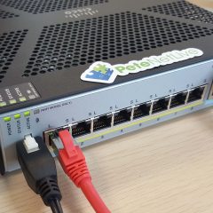
Cisco Firepower 1010 (FTD) Initial Setup

KB ID 0001678


If you’re here you’ve either purchased a new Cisco Firepower device running FTD (FirePower Threat Defence) or have re-imaged your Firepower device from ASA to FTD code.

On its factory defaults, the unit will have the following settings.

  • Inside IP address (VLAN 1) 192.168.1.1 (on all interfaces from 2 to 8).
  • Outside IP Address set to DHCP in interface 1.
  • Management IP address 192.168.45.1 on the Management Interface.
  • DHCP Scopes on both the inside and management interfaces (192.168.1.x and 192.168.45.x respectively).

  1. Power Connector.
  2. 8 x Gigabit Ethernet ports: Normally GigabitEthernet 1/1 will be for the WAN, GigabitEthernet 1/2 though 1/8 will be for the LAN (with 1/7 and 1/8 being PoE).
  3. Management Port.
  4. Console Port (RJ45).
  5. Console Port (Mini USB).
  6. USB Port (useful for upgrades, and backups).
  7. Kensington Lock: Seriously? I’ve not seen one of these since about 2005, does anyone still use them?
  8. Reset Button: Depress for 3 seconds reverts the firewall to its factory settings, (and preserves the config apparently).
  9. Status Lights, (another reason not to put things on top of it!) Though you will notice there’s some on the back also. Note: When all lights are solid the firewall is operational, when the centre light is blinking, it’s still booting).

FirePower 1010 Setup

I will be deploying this as a stand alone FTD firewall, that will be managed locally on the device itself via FDM (Firepower Device Manager) and not via an FMC (Firepower Management Center) appliance.

Smart Licensing: If you’re not already familiar with Cisco Smart Licensing, I’ve covered it in more depth here. Set yourself up a free Smart License Account, and generate a token, copy it to the clipboard, (we will need it in a minute).

Connect to the firewall via a LAN port on https://192.168.1.1, or via the Management port on https://192.168.45.1 (unless you have ran though the FTD setup at command line, and have already changed the management IP).

Default usernames, (you will be asked to change them) are;

  • Username: admin
  • Password: Admin 123

Scroll down.

Here I’m accepting the default Outside/Public Interface settings of DHCP enabled, with IPv6 disabled, if yours has a static IP, or you want to user IPv6 then change the settings accordingly > Next.

I’ll accept the defaults here, be advised those NTP servers may take a little while to ‘go-green’ (you will see what I mean later) > Next.

I’m going to do this manually in a minute, so we can skip this > Next.

Note: The unit will have a default policy of let everything out (sourced from inside), and nothing in (sourced from outside) we will leave that as it is, as a decent start point.

Stanalone device > Configure Interfaces.

Note: Below I’m going to REMOVE the DHCP Scope, then change the ‘inside’ IP address (to avoid errors). Then later I will add the new DHCP scope back in again.

VLANs > Vlan1 > Edit. > DHCP section > Edit > Remove.

You can now set the inside IP address accordingly. (Don’t panic you wont lose connectivity yet!) > OK.

Now you need to Save/Commit the changes, and Deploy them. Now you will lose connectivity, if you have changed the inside IP address, so manually give yourself an IP address on the new network, and reconnect to the firewall.

Note: Update: Pleas ensure tha management is allowed in VLAN1 before proceeding (System Settings -> Management Access -> Data Interfaces.)

Cisco Firepower Setup DHCP

Create a new DHCP Scope: Should you require the firewall to be a DHCP server, log back in to the new internal IP address > System Settings > DHCP Server.

Create DHCP Server > Enable DHCP Server > Enter the new scope > OK.

Remember to commit the changes, and deploy them again!

Cisco Firepower FTD Licensing

Thankfully this is MUCH easier than doing the same thing while running ASA Code (on the same hardware!) > Smart Licence > View Configuration.

Register Device.

Paste in your token, (from above) > Set your location > Register Device. Go and have a coffee, it will look like it’s broken/not worked for a few minutes.

After a while you should see this;

There will be some outstanding changes to save and deploy also, now the unit is registered.

Back in the Cisco Smart Licence portal, it should look a bit like this;

Once fully complete and operational, all connected interfaces should have all the options ‘go-green’. For me the NTP servers took a while!

Note: Obviously the interfaces in orange are not in use!


Related Articles, References, Credits, or External Links

NA

GNS3 – Assign an IP Address to Linux Microcore QEMU Guest

KB ID 0000932 

Problem

The whole point of having these guest machines is for testing communications, putting an IP address on them so you can ping things, is a pretty basic step.

Solution

1. Console in, and execute the following commands, obviously change the IP addresses to the ones you require.

[box]

sudo su
ifconfig eth0 10.10.10.10 netmask 255.0.0.0 up
route add ip default gw 10.10.10.1
route add default gw 10.10.10.1

[/box]

Related Articles, References, Credits, or External Links

NA

Changing the IP Address / Subnet Mask of a Cisco CSC Module

KB ID 0000781 

Problem

I had a client re-address their network this weekend, I was asked to make the relevant changes on the firewall. I know the CSC has a web interface, but as I usually work at command line I wanted to work out how to do it that way.

Solution

In the example below I will change the CSC module form 192.168.1.254/24 to 172.16.1.254/16.

1. Connect to the ASA, and check that the CSC module is up and healthy.

Note: Due the the limitations of HTML the output on you ASA will look a little neater like this.

[box]

User Access Verification

Password:
Type help or '?' for a list of available commands.
Petes-ASA> enable
Password: *******
Petes-ASA# show module 1 detail
Getting details from the Service Module, please wait...
ASA 5500 Series Content Security Services Module-10
Model: ASA-SSM-CSC-10-K9
Hardware version: 1.0
Serial Number: JAF1443AXXX
Firmware version: 1.0(11)5
Software version: CSC SSM 6.6.1125.0
MAC Address Range: d0d0.fdfe.a557 to d0d0.fdfe.a557
App. name: CSC SSM
App. Status: Up
App. Status Desc: CSC SSM scan services are available
App. version: 6.6.1125.0
Data plane Status: Up
Status: Up
HTTP Service: Up
HTTPS Service: Up
Mail Service: Up
FTP Service: Up
Activated: Yes
Mgmt IP addr: 192.168.1.254
Mgmt web port: 8443
Peer IP addr: <not enabled>

[/box]

2. Connect to the CSC module and choose option 1 (Network Settings). Note: the username is cisco and the password will be the password you use to log onto the CSC web console.

[box]

Petes-ASA# session 1
Opening command session with slot 1.
Connected to slot 1. Escape character sequence is 'CTRL-^X'.

login: cisco
Password:*******
***NOTICE***
This product contains cryptographic features and is subject to United States
and local country laws governing import, export, transfer and use. Delivery
of Cisco cryptographic products does not imply third-party authority to import,
export, distribute or use encryption. Importers, exporters, distributors and
users are responsible for compliance with U.S. and local country laws. By using
this product you agree to comply with applicable laws and regulations. If you
are unable to comply with U.S. and local laws, return this product immediately.

A summary of U.S. laws governing Cisco cryptographic products may be found at:
http://www.cisco.com/wwl/export/crypto/tool/stqrg

If you require further assistance please contact us by sending email to
export@cisco.com.


Trend Micro InterScan for Cisco CSC SSM Setup Main Menu
---------------------------------------------------------------------

1. Network Settings
2. Date/Time Settings
3. Product Information
4. Service Status
5. Password Management
6. Restore Factory Default Settings
7. Troubleshooting Tools
8. Reset Management Port Access Control List
9. Ping
10. Exit ...

Enter a number from [1-10]: 1

[/box]

3. Enter ‘y’ for yes to change the settings > Type in the new details (just press enter to proceed without changing any of the options).

[box]

Network Settings
---------------------------------------------------------------------

IP 192.168.1.254
Netmask 255.255.255.0
Hostname CSC
Domain name petenetlive.com
MAC address D0:D0:FD:FE:A5:57

Primary DNS 192.168.1.3

Gateway 192.168.1.1
No Proxy

Do you want to modify the network settings? [y|n] y

Network Settings
---------------------------------------------------------------------

Enter the SSM card IP address: (default:192.168.1.254)172.16.1.254
Enter subnet mask: (default:255.255.255.0) 255.255.0.0
Enter host name: (default:CSC)
Enter domain name: (default:petenetlive.com)
Enter primary DNS IP address: (default:192.168.0.3)172.16.1.10
Enter optional secondary DNS IP address:
Enter gateway IP address: (default:192.168.0.254)172.16.1.1
Do you use a proxy server? [y|n] (default:no)
Stopping services:
OK
Applying network settings ...
Starting services: OK

[/box]

4. Press Enter to return to the main menu, you can check the change was successful by selecting option 1 again, but this time enter ‘n’ when asked if you want to change anything.

[box]

Press Enter to continue ...

Trend Micro InterScan for Cisco CSC SSM Setup Main Menu
---------------------------------------------------------------------

1. Network Settings
2. Date/Time Settings
3. Product Information
4. Service Status
5. Password Management
6. Restore Factory Default Settings
7. Troubleshooting Tools
8. Reset Management Port Access Control List
9. Ping
10. Exit ...

Enter a number from [1-10]: 1

Network Settings
---------------------------------------------------------------------

IP 172.16.1.254
Netmask 255.255.0.0
Hostname CSC
Domain name petenetlive.com
MAC address D0:D0:FD:FE:A5:57

Primary DNS 172.16.1.10

Gateway 172.16.1.1
No Proxy

Do you want to modify the network settings? [y|n] n

[/box]

5. Exit the main menu, then choose reboot (Note: This reboots the module NOT the ASA.)

[box]

Trend Micro InterScan for Cisco CSC SSM Setup Main Menu
---------------------------------------------------------------------

1. Network Settings
2. Date/Time Settings
3. Product Information
4. Service Status
5. Password Management
6. Restore Factory Default Settings
7. Troubleshooting Tools
8. Reset Management Port Access Control List
9. Ping
10. Exit ...

Enter a number from [1-10]: 10

Exit Options
---------------------------------------------------------------------

1. Logout
2. Reboot
3. Return to Main Menu

Enter a number from [1-3]: 2
Please wait while rebooting.
Remote card closed command session. Press any key to continue.
Command session with slot 1 terminated.

[/box]

6. You can check its status, for a while it will say its ‘unresponsive’. Eventually it will say all services are ‘up’

[box]

Petes-ASA# show module 1 detail
Getting details from the Service Module, please wait...
Unable to read details from slot 1
ASA 5500 Series Content Security Services Module-10
Model: ASA-SSM-CSC-10-K9
Hardware version: 1.0
Serial Number: JAF1443AXXX
Firmware version: 1.0(11)5
Software version: CSC SSM 6.6.1125.0
MAC Address Range: d0d0.fdfe.a557 to d0d0.fdfe.a557
App. name: CSC SSM
App. Status: Not Applicable
App. Status Desc: Not Applicable
App. version: 6.6.1125.0
Data plane Status: Not Applicable
Status: Unresponsive <<<<

Petes-ASA# show module 1 detail
Getting details from the Service Module, please wait...
ASA 5500 Series Content Security Services Module-10
Model: ASA-SSM-CSC-10-K9
Hardware version: 1.0
Serial Number: JAF1443AXXX
Firmware version: 1.0(11)5
Software version: CSC SSM 6.6.1125.0
MAC Address Range: d0d0.fdfe.a557 to d0d0.fdfe.a557
App. name: CSC SSM
App. Status: Up
App. Status Desc: CSC SSM scan services are available
App. version: 6.6.1125.0
Data plane Status: Up
Status: Up
HTTP Service: Up
HTTPS Service: Up
Mail Service: Up
FTP Service: Up
Activated: Yes
Mgmt IP addr: 172.16.1.254
Mgmt web port: 8443
Peer IP addr: <not enabled>
Petes-ASA#

[/box]

7. Finally you can check the IP address, from the web console.

Related Articles, References, Credits, or External Links

NA

Cisco ASA – Changing VPN IP Addresses

KB ID 0000391

Problem

I had a client the other week with about 25 sites, his core site was changing ISP and therefore changing its IP address. On the main site this is pretty straightforward, just change the outside interfaces IP address, sub net mask and the default route (That’s the default gateway for non cisco-ites).

All well and good, but what about his other 24 sites? They all had VPN’s back to the main site, and all these VPN’s were “hairpinned” together for “spoke to spoke” communication.

Well you can simply delete the VPNs and recreate them, but multiply that by 24 – then add on all the extra config for the hairpins and that’s a massive amount of work (and for the client a LOT of downtime.) So a swift config change on the remote sites is a much better idea.

For Cisco PIX firewalls running version 6 click here.

Solution

Option 1 From Command Line (for ASDM see below)

In this example my main site (123.123.123.123) has changed its IP address to (234.234.234.234), and I need to reconfigure the remote site(s).

1. First – you need to understand a couple of things, for a VPN to work, it needs the IP address of the “Other End” of the tunnel in two places.

a. In the Cryptomap.
b. In a Tunnel Group.

2. First lets find the cryptomap, connect to the ASA, log in go to enable mode then configuration mode.

[box]

RemoteSite>
RemoteSite> enable
Password: ***********
RemoteSite# configure terminal
RemoteSite(config)#[/box]

3. To see all the cryptomaps issue a “show run crypto map” command. (you may see more or less depending on the amount of VPN tunnels you have.

[box]

RemoteSite(config)# show run crypto map
crypto map outside_map 1 match address outside_1_cryptomap
crypto map outside_map 1 set pfs
crypto map outside_map 1 set peer 111.111.111.111
crypto map outside_map 1 set transform-set ESP-3DES-SHA
crypto map outside_map 2 match address outside_2_cryptomap
crypto map outside_map 2 set pfs
crypto map outside_map 2 set peer 123.123.123.123 <<<< Here it is!!!
crypto map outside_map 2 set transform-set ESP-3DES-SHA
crypto map outside_map 3 match address outside_3_cryptomap
crypto map outside_map 3 set pfs
crypto map outside_map 3 set peer 133.133.133.133
crypto map outside_map 3 set transform-set ESP-3DES-SHA
crypto map outside_map 4 match address outside_4_cryptomap
crypto map outside_map 4 set pfs
crypto map outside_map 4 set peer 144.144.144.144
crypto map outside_map 4 set transform-set ESP-3DES-SHA
RemoteSite(config)#[/box]

4. From the example above we can see the tunnel we want to change is using “outside_map 2” so lets remove the entry for the old IP address and put one in for the new IP address.

[box]

RemoteSite(config)# no crypto map outside_map 2 set peer 123.123.123.123
WARNING: The crypto map entry will be incomplete!
RemoteSite(config)# crypto map outside_map 2 set peer 234.234.234.234
RemoteSite(config)#[/box]

5. That’s the cryptomap changed, now for the tunnel group. You can see all your tunnel groups with a “sho run tun” command.

[box]

RemoteSite(config)# sho run tun
tunnel-group DefaultL2LGroup ipsec-attributes
isakmp keepalive threshold 20 retry 2
tunnel-group DefaultRAGroup ipsec-attributes
isakmp keepalive threshold 20 retry 2
tunnel-group DefaultWEBVPNGroup ipsec-attributes
isakmp keepalive threshold 20 retry 2
tunnel-group 111.111.111.111 type ipsec-l2l
tunnel-group 111.111.111.111 ipsec-attributes
pre-shared-key *****
tunnel-group 123.123.123.123 type ipsec-l2l <<<< Here it is!!!
tunnel-group 123.123.123.123 ipsec-attributes
pre-shared-key *****
tunnel-group 133.133.133.133 type ipsec-l2l
tunnel-group 133.133.133.133 ipsec-attributes
pre-shared-key *****
isakmp keepalive threshold 20 retry 2
tunnel-group 144.144.144.144 type ipsec-l2l
tunnel-group 144.144.144.144 ipsec-attributes
pre-shared-key *****[/box]

6. To delete a tunnel group, you use the “clear config tunnel-group” command.

Note: Before you delete it, make sure you know the pre shared key / shared secret – to see this, issue a “more system:running-config” command.

[box]

RemoteSite(config)# clear config tunnel-group 123.123.123.123
RemoteSite(config)#[/box]

7. Then simply create a new tunnel group, with the new IP address, and the same shared secret / pre shared key as the old one.

[box]

RemoteSite(config)# tunnel-group 234.234.234.234 type ipsec-l2l
RemoteSite(config)# tunnel-group 234.234.234.234 ipsec-attributes
RemoteSite(config-tunnel-ipsec)# pre-shared-key 123456789
[/box]

8. Save the new config with a “write mem” command

[box]

RemoteSite(config)# write mem

Building configuration...

Cryptochecksum: f3645705 ae6bafda c5606697 ecd61948
9830 bytes copied in 1.550 secs (9830 bytes/sec)
[OK]
RemoteSite(config)#

[/box]

9. Job done!

Well that didn’t seem very quick? No, but for the sake of explanation I did go a little deep, if you have multiple sites, just have the following in notepad.

configure terminal
no crypto map outside_map 2 set peer 123.123.123.123
crypto map outside_map 2 set peer 234.234.234.234
clear config tunnel-group 123.123.123.123
tunnel-group 234.234.234.234 type ipsec-l2l
tunnel-group 234.234.234.234 ipsec-attributes
pre-shared-key 123456789
write mem

Then simply jump from site to site changing the cryptomap name and shared secret for each one. If you get all this info first, you can migrate hundreds of sites in minutes, (That’s why I prefer command line to GUI ASDM).

Option 2 From ASDM

1. Connect to the ASDM, Configuration > Site-to-Site VPN > Advanced > Crypto Maps > Select the cryptomap going to 123.123.123.123 > Edit > Add the new IP Address.

2. Remove the old one > OK > Apply.

3. Configuration > Site-to-Site VPN > Advanced > Tunnel Groups > Select the old one > Delete > Apply.

4. Then to add a new one > Add > Set the Tunnel group name to the new IP > Enter the shared secret > OK > Apply.

5. Finally Save the changes > File > Save running configuration to Flash.

Cisco PIX (Version 6)

For older firewalls you will notice there is no “Tunnel-Group”, these came in with version 7. The process is similar, again you have to change the peer entry in the cryptomap, but you also need to set an isakmp peer.

no crypto map outside_map 20 set peer 123.123.123.123
crypto map outside_map 20 set peer 234.234.234.234
no isakmp key ******** address 123.123.123.123 netmask 255.255.255.255
isakmp key 123456789 address 234.234.234.234 netmask 255.255.255.255


Related Articles, References, Credits, or External Links

NA