
SRX Cluster KB ID 0000990
Problem
I’ve had very little exposure to JUNOS and Juniper equipment, and later in the year I have to deploy some for a client in a failover cluster. So I had a good look round on the Internet, and found loads of good blog posts and KB articles like this one. The problem is they are all geared to setting up a cluster, they ASSUME you then know about security zones, how to add default routes, and setup NAT etc. So they don’t cover that. Yes you then can set up a cluster, but it has no IP addresses, and you cant pass any traffic though it! Hopefully this will redress the balance.
Solution: SRX Cluster
Before you start, you obviously need two physical firewalls running the same OS, and this whole procedure is carried out from command line, (I’m using the console cable).
Things that took me a while to grasp, that you need to know.
1. The SRX I’m using has 16 ports numbered ge-0/0/0 to ge-0/0/15, when you cluster them the ports on the secondary firewall (node1) are renumbered to ge-5/0/0 to ge-5/0/16.
2. As soon as you cluster the firewalls the first port (on both) is reserved for management. That’s ge-0/0/0 and ge-5/0/0 they are then refereed to as fxp0.
3. As soon as you cluster the firewalls the second port (on both) is reserved for the firewalls control plane. That’s ge-0/0/1 and ge-5/0/1 they are then refereed to as fxp1.
4. You need to dedicate another port on both firewalls for the firewalls data link this can be any port, but to keep things simple I’ll use the next free port on both firewalls (ge-0/0/2 and ge-5/0/2). These will then be referred to as fab0 and fab1 (respectively).

Thats the clustering side of things, what about the networks I’m going to connect to the firewall. Take a look at this diagram;
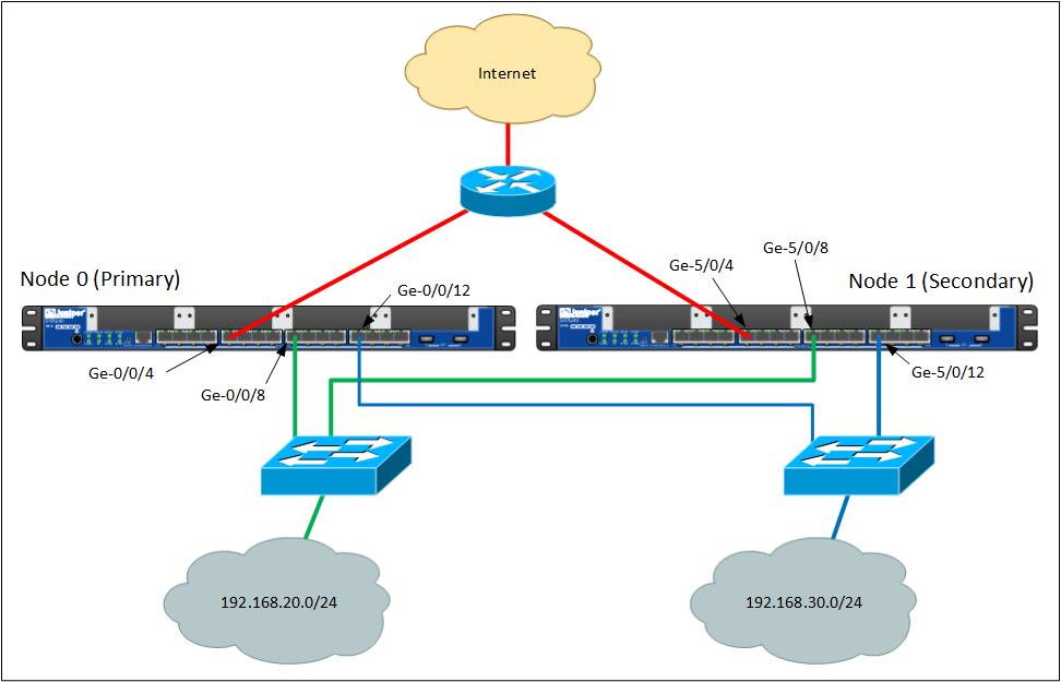
Both the firewalls have a connection to each network (which makes sense if they are going to fail over). I’ve got an ‘outside’ network that connects to the Internet. ‘Inside’ I’ve got two networks, (most people reading this will have one, but remember this is practice for a live client, and they have two data LANs).
As all the networks are connected in two places, where do you assign IP addresses? Well above you can see the outside connections are plugged into ge-0/0/4 and ge-5/0/4. You add both these physical interfaces to a Reth (Redundant Ethernet Interface), and you assign the IP to that. So I have three Reth interfaces, (Reth0 for outside, Reth1 for the first inside network, Reth2 for the second inside interface).
So only Reth interfaces have IP addresses? Well no, the two fxp0 interfaces on each physical firewall, also get an IP address (for out of band management), and it’s a different one for each firewall.
Step 1: Setup SRX Cluster.
1. Before we start you need to delete the existing interfaces from the config (ALL of them), otherwise you will get some errors later on when you try and commit (save) the firewall config. Also remove the hostname, we will set that in a minute.
delete interfaces ge-0/0/0
delete interfaces ge-0/0/1
---Repeat for the rest of the interfaces---
delete interfaces ge-0/0/14
delete interfaces ge-0/0/15
delete system host-name
2. Connect ge-0/0/0 to management network > Connect ge-5/0/0 to management network >
Connect ge-0/0/1 on Primary to ge-5/0/1 on Standby, (this can’t be changed and will be the fxp0 connection) > Connect ge-0/0/2 on Primary to ge-5/0/2 on Standby (this can be changed but will be the fab0 and fab1 connection).
3. Carry out the following procedure on BOTH firewalls. This sets the host names of the firewalls and the IP addresses of the management interfaces.
set groups node0 system host-name FW-A
set groups node0 interfaces fxp0 unit 0 family inet address 192.168.254.1/24
set groups node1 system host-name FW-B
set groups node1 interfaces fxp0 unit 0 family inet address 192.168.254.2/24
set apply-groups "${node}"
4. On FW-A (the primary node0) turn on clustering.
set chassis cluster cluster-id 1 node 0 reboot
5. On FW-B (the secondary node1) turn on clustering.
set chassis cluster cluster-id 1 node 1 reboot
6. Back on FW-A (the remainder of the config will be done on node0), set the configuration for the data link, notice I’m deleting the interface again, (I had a lot of bother with this so let’s play it safe). Then I’m saving the changes with a ‘commit’ command, because at this point if something is wrong it will tell you.
delete interfaces ge-0/0/2
set interfaces fab0 fabric-options member-interfaces ge-0/0/2
set interfaces fab1 fabric-options member-interfaces ge-5/0/2
commit
Step 2 SRX Cluster : Create Redundancy Groups
1. Redundancy group 0 is created by default so set the priority for that one first.
root@FW-A# set chassis cluster redundancy-group 0 node 0 priority 100
root@FW-A# set chassis cluster redundancy-group 0 node 1 priority 1
2. Create a new redundancy group that the Reth interfaces will use.
root@FW-A# set chassis cluster redundancy-group 1 node 0 priority 100
root@FW-A# set chassis cluster redundancy-group 1 node 1 priority 1
Step 3 SRX Cluster : Define and Add Physical Interfaces to the Reth Interfaces
1. Define the number of Reth interfaces (two inside and one outside).
root@FW-A# set chassis cluster reth-count 32. Allocate Reth0 to the physical interfaces (for outside).
{primary:node0}[edit]
root@FW-A# edit interfaces
{primary:node0}[edit interfaces]
root@FW-A# set ge-0/0/4 gigether-options redundant-parent reth0
root@FW-A# set ge-5/0/4 gigether-options redundant-parent reth0
3. Apply Redundancy group 1 to Reth0 and give it an IP Address.
root@FW-A# set reth0 redundant-ether-options redundancy-group 1
root@FW-A# set reth0 unit 0 family inet address 123.123.123.123/24
4. Let’s see if that worked.
root@FW-A# show chassis cluster
reth-count 3;
redundancy-group 0 {
node 0 priority 100;
node 1 priority 1;
}
redundancy-group 1 {
node 0 priority 100;
node 1 priority 1;
}
5. Setup Reth1 (inside). Add the physical interfaces, and apply redundancy group 1 (again).
{primary:node0}[edit]
root@FW-A# edit interfaces
{primary:node0}[edit interfaces] root@FW-A# set ge-0/0/8 gigether-options redundant-parent reth1 root@FW-A# set ge-5/0/8 gigether-options redundant-parent reth1 root@FW-A# set reth1 redundant-ether-options redundancy-group 1 root@FW-A# set reth1 unit 0 family inet address 192.168.20.1/24
6. Setup Reth2 (inside). Add the physical interfaces, and apply redundancy group 1 (again) then save the changes.
{primary:node0}[edit]
root@FW-A# edit interfaces
{primary:node0}[edit interfaces] root@FW-A# set ge-0/0/12 gigether-options redundant-parent reth2 root@FW-A# set ge-5/0/12 gigether-options redundant-parent reth2 root@FW-A# set reth2 redundant-ether-options redundancy-group 1 root@FW-A# set reth2 unit 0 family inet address 192.168.50./24 {primary:node0}[edit interfaces] root@FW-A# exit {primary:node0}[edit] root@FW-A# commit node0: commit complete
{primary:node0}[edit] root@FW-A#
7. Then add the six physical interfaces that make up all the Reth interfaces to the redundancy group 1, and give each interface a ‘weighting’ of 255.
{primary:node0}[edit]
root@FW-A#
set chassis cluster redundancy-group 1 interface-monitor ge-0/0/4 weight 255
primary:node0}[edit] root@FW-A# set chassis cluster redundancy-group 1 interface-monitor ge-0/0/8 weight 255
{primary:node0}[edit] root@FW-A# set chassis cluster redundancy-group 1 interface-monitor ge-0/0/12 weight 255
{primary:node0}[edit] root@FW-A# set chassis cluster redundancy-group 1 interface-monitor ge-5/0/4 weight 255
{primary:node0}[edit] root@FW-A# set chassis cluster redundancy-group 1 interface-monitor ge-5/0/8 weight 255
{primary:node0}[edit] root@FW-A# set chassis cluster redundancy-group 1 interface-monitor ge-5/0/12 weight 255
Step 4: Add a ‘Default Route’ to the Internet.
1. To get traffic out to the Internet. the cluster needs the IP of its ‘next-hop’, (usually the router supplied by your ISP).
Note: If you’re anything like me after you enter this you will try and ‘ping’ the router from the firewall, or ping an Internet. IP address, at this point that wont work, (you need to allocate interfaces to security zones first).
root@FW-A# set routing-options static route 0.0.0.0/0 next-hop 123.123.123.1
Step 5 SRX Cluster : Add interfaces to Security Zones and Allow Traffic Out
Note: I’m simply allowing all traffic out.
1. Make sure the Security Zones ‘Trust’ and ‘Untrusted’ Exist
root@FW-A# show security zones
or
root@FW-A# run show security zones
2. Add the Reth0 Interface to the Untrusted zone.
root@FW-A# set security zones security-zone untrust interfaces reth0.0
3. Allow traffic.
{primary:node0}[edit]
root@FW-A# set security zones security-zone untrust host-inbound-traffic system-services all
root@FW-A# set security zones security-zone untrust host-inbound-traffic protocols all
4. You can check the changes before you commit them.
{primary:node0}[edit]
root@FW-A# show | compare
[edit security zones security-zone untrust]
+ host-inbound-traffic {
+ system-services {
+ all;
+ }
+ protocols {
+ all;
+ }
+ }
+ interfaces {
+ reth0.0;
+ }
Save the changes

{primary:node0}[edit] root@FW-A# commit node0: configuration check succeeds node1: commit complete node0: commit complete
5. Then add Reth1 and Reth2 to the Trusted zone and repeat the process to allow all traffic.
root@FW-A# set security zones security-zone trust interfaces reth1.0
root@FW-A# set security zones security-zone trust interfaces reth2.0
root@FW-A# set security zones security-zone trust host-inbound-traffic system-services all
root@FW-A# set security zones security-zone trust host-inbound-traffic protocols all
6. Let’s check to see all that worked.
{primary:node0}[edit] root@FW-A# show security policies from-zone trust to-zone untrust policy trust-to-untrust { match { source-address any; destination-address any; application any; } then { permit; } }
{primary:node0}[edit] root@FW-A# show security policies from-zone trust to-zone untrust { policy trust-to-untrust { match { source-address any; destination-address any; application any; }< then { permit; } } }
Step 6 Allow Remote Management
1. We have two interfaces dedicated to out of band management, and we gave them an IP address earlier. Here I’m allowing remote administration via web to the J-Web console.
root@FW-A# set system services web-management https interface fxp0.0
Step 7 Perform NAT on ‘Outgoing’ traffic.
1. Here we are doing what Juniper call ‘Source NAT‘ where we translate many addresses to one, (as in this case, but it can be a ‘pool’ of IP addresses). For the Cisco heads (like me) we are doing PAT.
Note: If you see Juniper mention ‘Destination NAT‘ they are usually talking about NATTING inbound traffic to one (or more) internal IP addresses.
set security nat source rule-set TRUST-TO-UNTRUST from zone untrust
set security nat source rule-set TRUST-TO-UNTRUST to zone trust

set security nat source rule-set TRUST-TO-UNTRUST rule PAT-INTERFACE match source-address 192.168.0.0/16
set security nat source rule-set TRUST-TO-UNTRUST rule PAT-INTERFACE match destination-address 0.0.0.0/0
set security nat source rule-set TRUST-TO-UNTRUST rule PAT-INTERFACE then source-nat interface
Related Articles, References, Credits, or External Links
NA