
KB ID 0000833
Problem
In the following procedure I’ll configure the following;
- HP 5412zl Switch.
- Cisco ASA 5510 Firewall.
- HP MSM720 Controller.
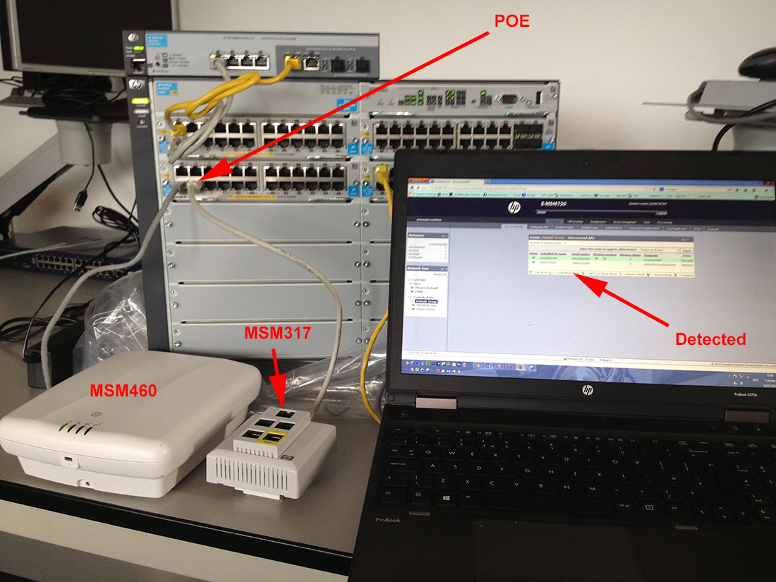
- HP MSM460 and MSM317 Access Points.
If you are configuring an MSM765zl or MSM775zl use the following article first.
HP MSM765zl and 775zl – Initial Setup and Routing
Assumptions
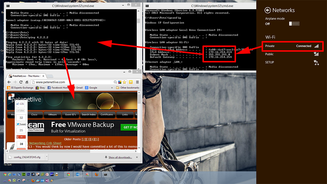
- Private SSID will be on the normal corporate LAN (In this case 172.16.254.0/24).
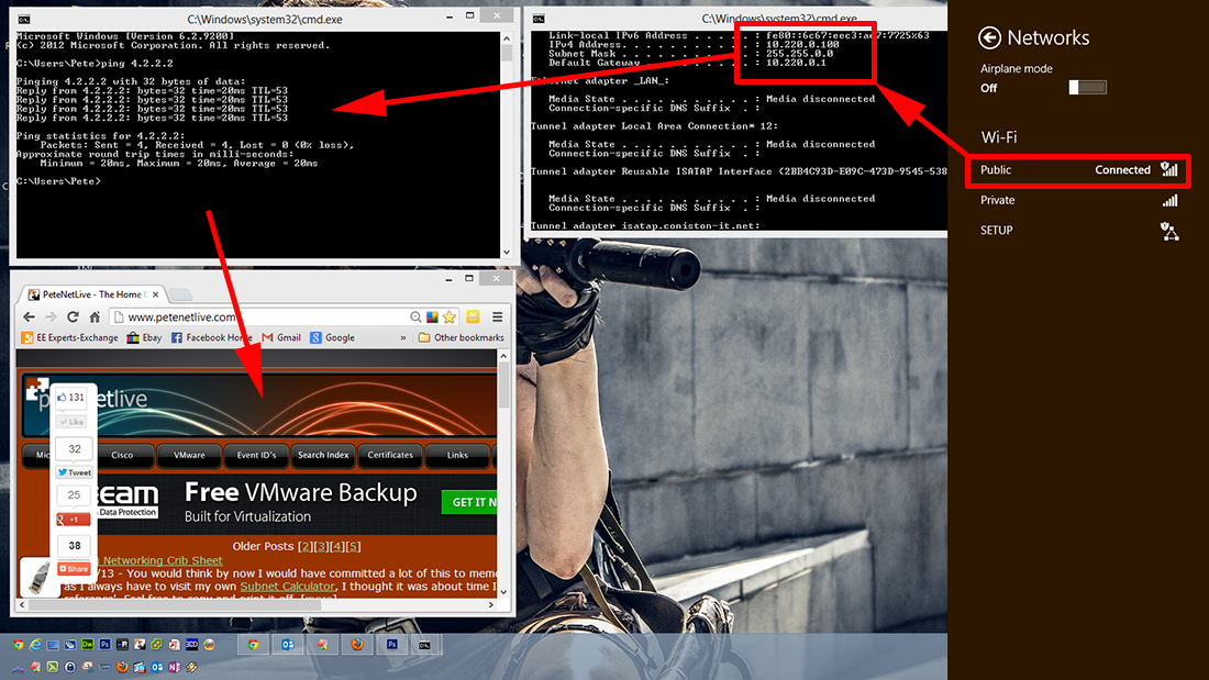
- Public SSID will get its IP addressing from the controllers DHCP Server. (10.220.0.0/16).
- The Wireless traffic will traverse the corporate LAN (After being natted on the controller) as 10.210.0.0/16.
- My LAN DNS Servers are 172.16.254.1 and 172.16.254.2.
Solution
HP Switch Configuration.
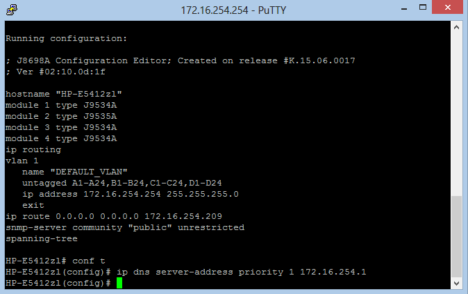
1. The switch must be performing LAN routing, if the LAN’s default gateway is a firewall that needs rectifying first. (where 172.16.254.200 is the firewall).

2. Switch must be able to resolve DNS queries.
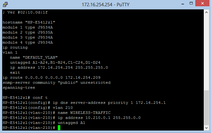
3. Declare a VLAN for the guest VLAN (210), name it, and give it an IP address > Add a Port (A1) to that VLAN which will connect to the Internet Port of the MSM Controller (Port5).
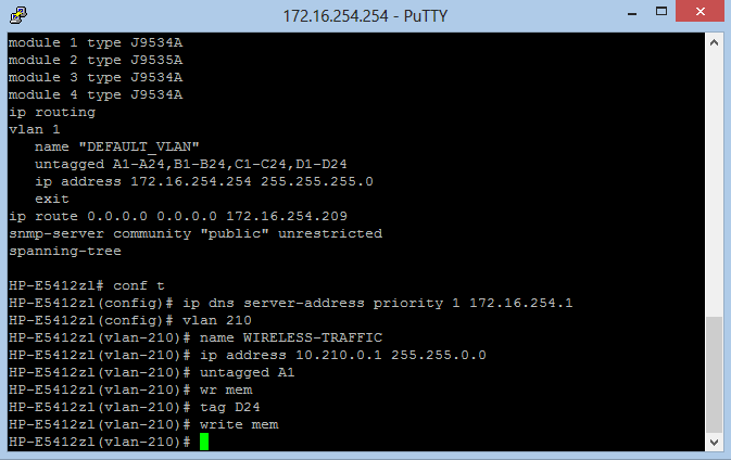
4. Tag This VLAN on the ‘Inter Switch’ Links from the core switch to the firewall/perimeter device.
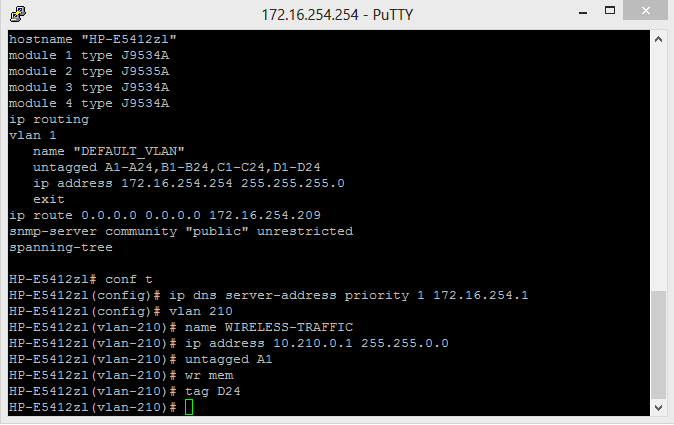
5. Save the Switch changes with a write mem command.
Configure the Cisco ASA To Allow the Wireless Traffic out.
Actions for different firewall vendors will vary but you need to achieve the following;
Make sure that a client on the 10.210.0.0/16 network can get access to the Internet
To do that you will need to achieve the following;
Make sure that the 10.210.0.0/16 network has http and https access allowed outbound on the firewall.
Make sure that 10.210.0.0/16 is getting NATTED through the firewall to the public IP address.
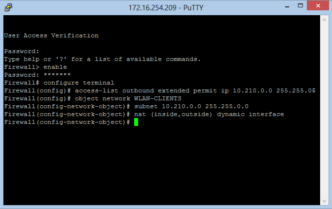
1. Connect to the firewall > Allow the Wireless Traffic out.
access-list outbound extended permit ip 10.210.0.0 255.255.0.0 any
Note: this permits ALL IP traffic you might prefer
access-list outbound extended permit ip 10.210.0.0 255.255.0.0 any eq http access-list outbound extended permit ip 10.210.0.0 255.255.0.0 any eq https
Note2: This also assumes you have an ACL called outbound applied to traffic that is destined outbound (show run access-group will tell you)

2. Perform NAT on the new wireless outbound traffic.
object network WLAN-CLIENTS subnet 10.210.0.0 255.255.0.0 nat (inside,outside) dynamic interface
Note: For Firewalls running versions older than 8.3 the NAT commands will be different, e.g.
nat (inside) 1 10.210.0.0 255.255.0.0
{Where you have a matching global (outside) 1 command in the config already}
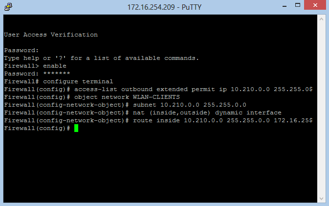
3. Allow the firewall to ‘route’ traffic back to the wireless clients. (where 172.16.254.254 is the core switch performing LAN routing).
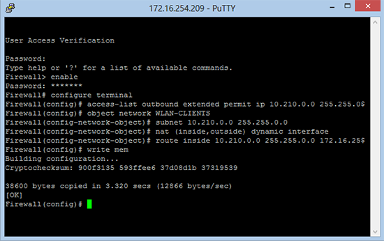
4. Save the changes.
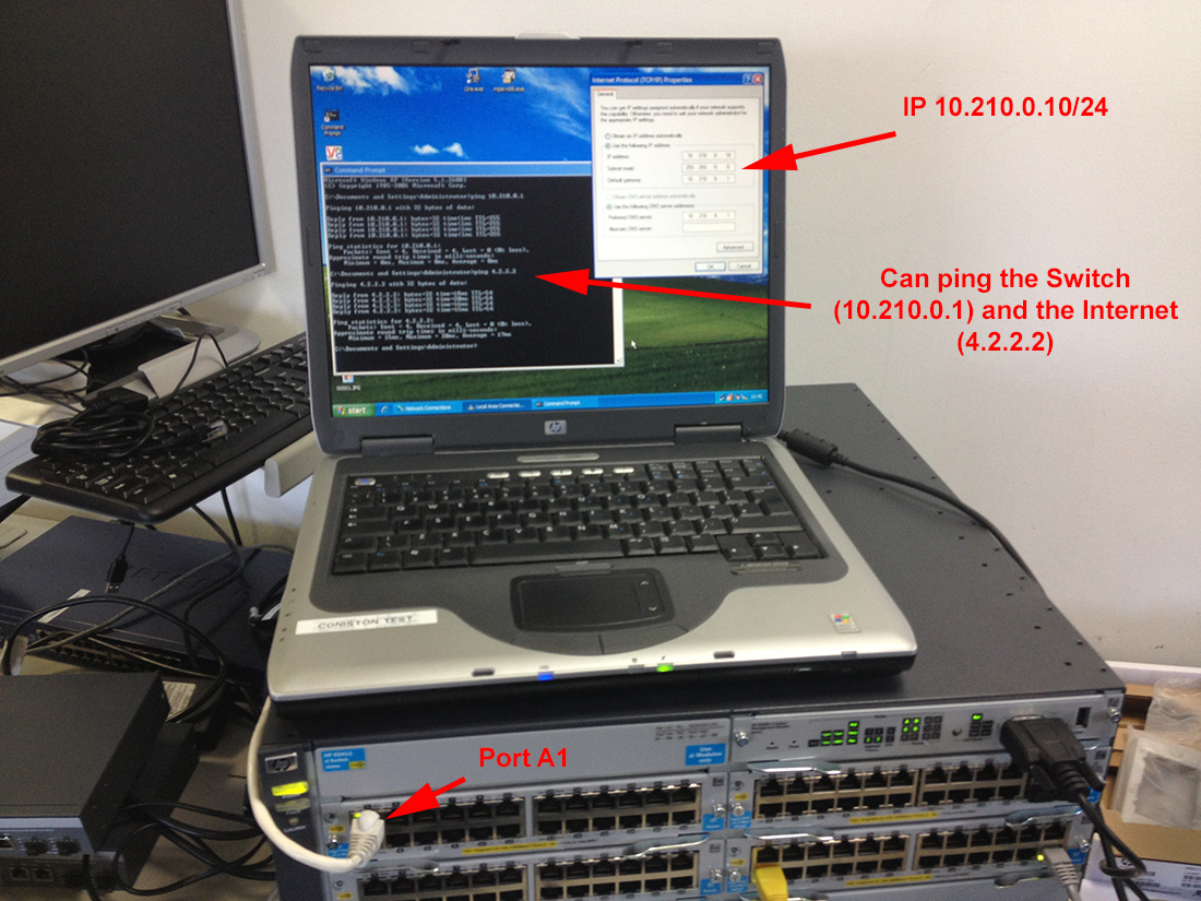
5. At this point plug a PC/Laptop into the core switch (Port A1) and make sure you can get Internet access (‘you will need a static IP on the 10.210.0.0 range).
Configure the HP MSM 720 Controller
MSM 720 Initial Setup and IP Addressing.
1. Connect to to the MSM 720 controller (Port 1) 192.168.1.1 (username admin, password admin).
2. Go though the initial setup > Stop when you get to the Automated workflows screen (simply press Home).
3. Setup Access Network: Home > Network > Access Network > Set the Addressing and Management IP addresses like so;
- Addressing 172.16.254.115/24
- Management address 172.16.254.116/25
Save.

Note: There’s two because you can separate the management traffic off to another subnet if you wish.
4. Connect Port 1 on the MSM controller to ANY normal port on the Switch (which will be untagged in VLAN 1) >Then connect to the Controller on its new IP https://172.16.254.115.
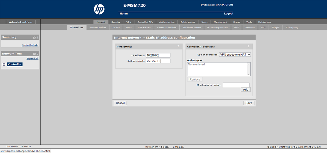
5. Setup Internet Network: Home > Network > Internet Network > Static.
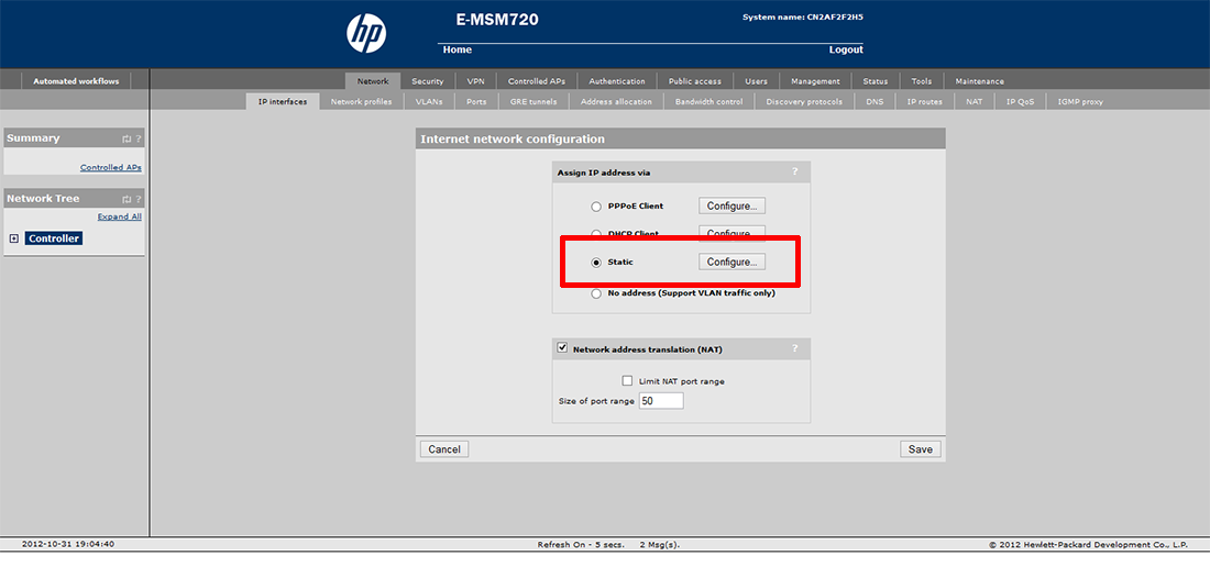
6. Configure > IP = 10.210.0.2 > Address Mask 255.255.0.0 > Save (don’t worry if you get a warning about DNS).
7. Connect Port 5 on the MSM to Port A1 on the switch (the one you untagged in VLAN 210).

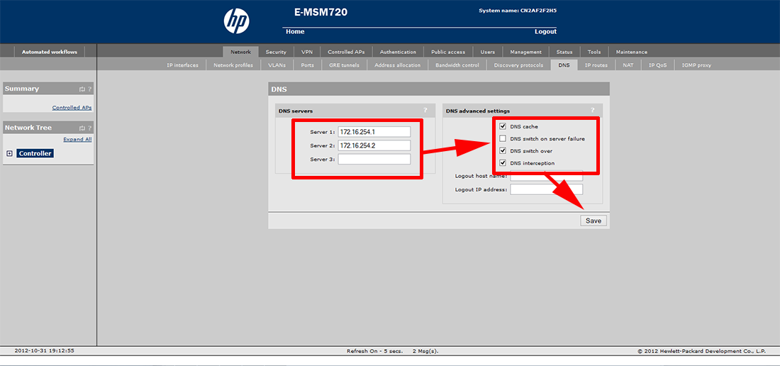
8. Setup DNS: Home > Network > DNS > Enter the Primary LAN DNS servers (172.16.254.1 and 172.16.254.2).
9. Tick DNS Cache > Tick DNS Switch over > Tick DNS interception > Save.
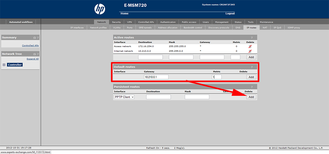
10. Setup Default Route: Home > Network > IP Routes > Add.
11. Enter 10.210.0.1 with a Metric of 1 > Add.
12. Setup DHCP (Note: you will create the scope later)
Obviously only complete this step if you want the Controller to act as a DHCP server for your ‘Public’ Wireless network.
Home> Network > Address allocation > Tick DHCP Server > Configure.
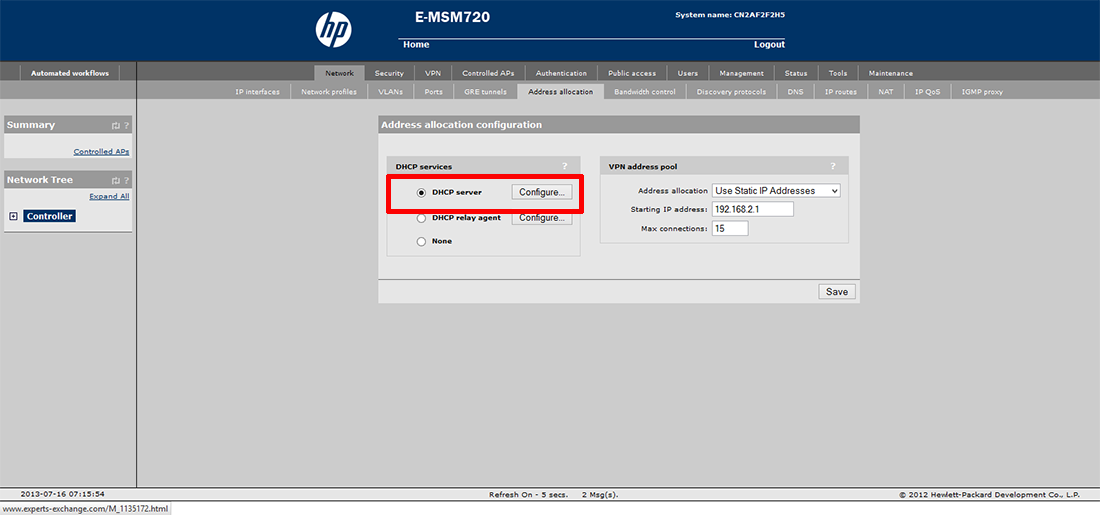
13. Enter the domain name > change Lease tome to 1500.
Note: At this point it automatically fills in DHCP Settings (these will NOT be used don’t panic!)
14. REMOVE the tick form Listen for DHCP Requests on ‘Access Network’
15. MAKE SURE there is a tick in the ‘Client data tunnel’ box > Save.

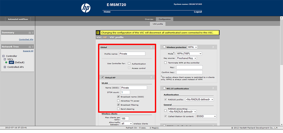
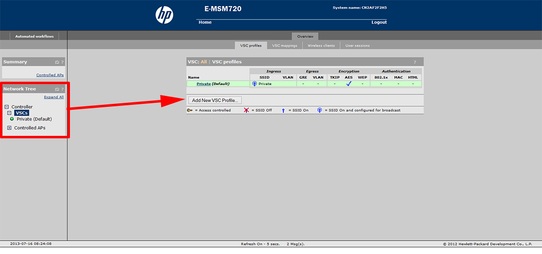
HP MSM 720 Configure Wireless Access Public and Private
For this procedure we will rename the default VSC which is called HP.
1. Home > Controller (on the left) > VSCs) > HP > Change the Profile name for HP to “Private” > Untick Authentication > Untick Access control.
2. Change the SSID from HP to ‘Private’ > Tick Broadcast Filtering.
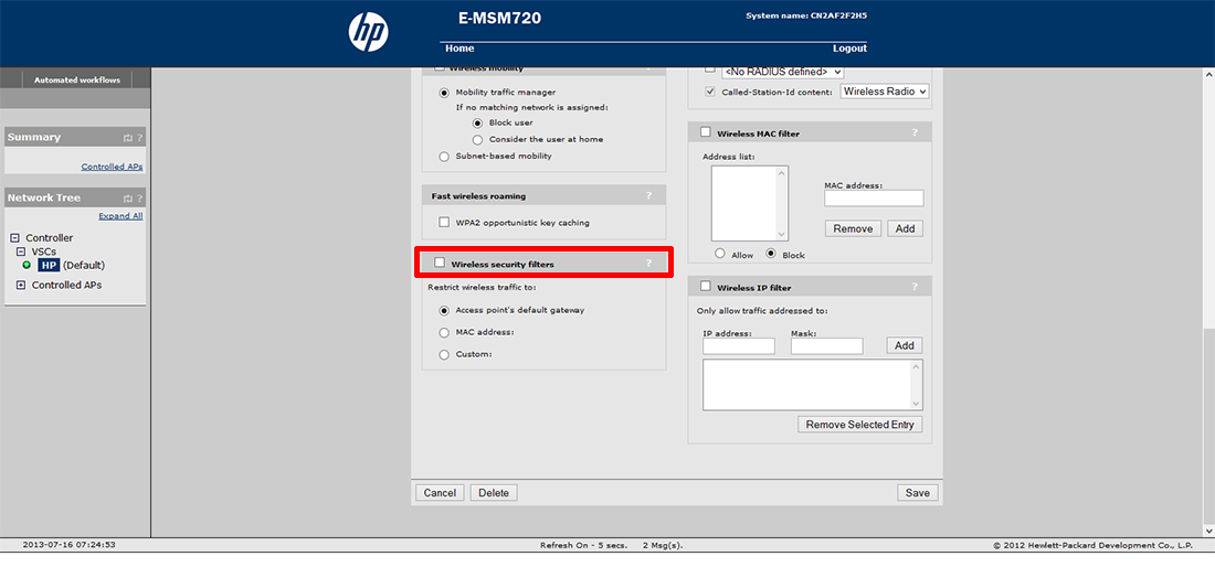
3. Ensure Wireless security filters is unticked.
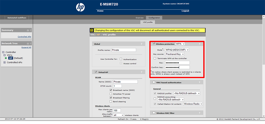
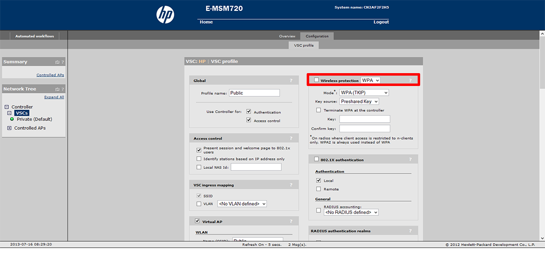
4. Tick Wireless Protection > Set the mode to WPA2 (AES/CCMP) > Change Key Source to ‘Preshared Key’ > Enter and confirm the WPA Password > Save (at the bottom of the screen).
5. Setup Public/Guest VSC: Home > VSC’s > Add New VSC Profile.
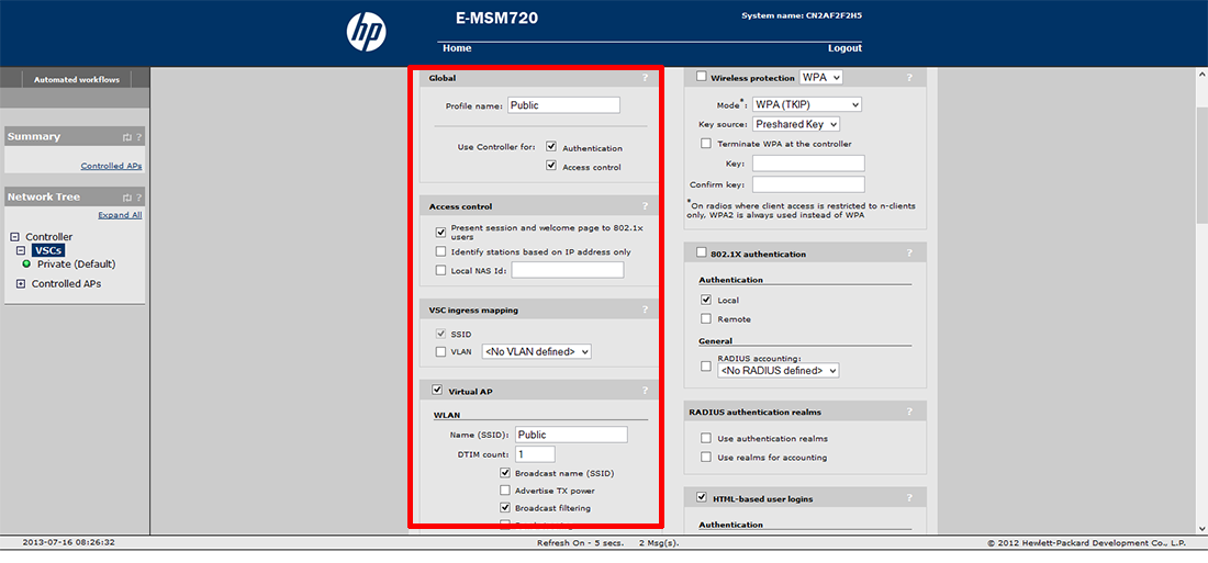
6. Set the profile name to ‘Public’ > MAKE SURE authentication and access control ARE ticked.
7. Change the SSID to Public > Tick broadcast filtering.
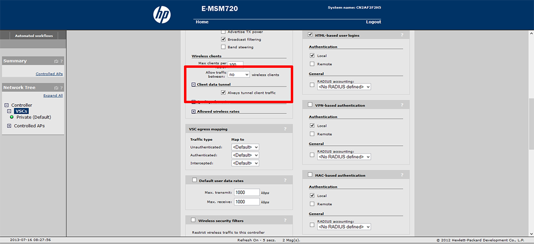
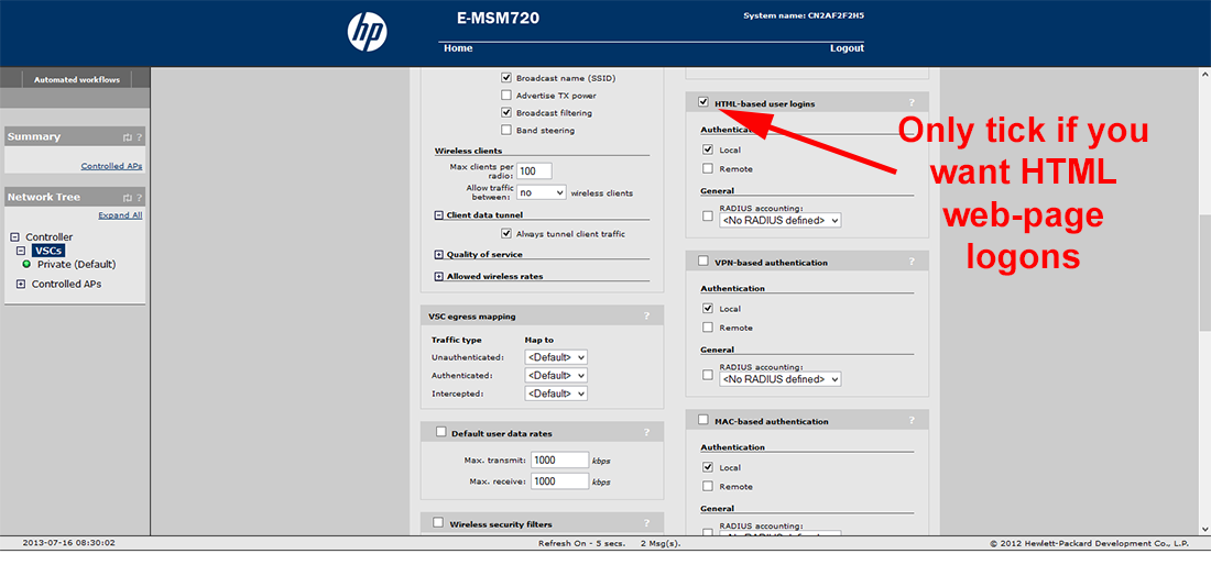
8. Change Allow Traffic between wireless clients to NO > Expand Client Data Tunnel > Tick ‘always tunnel client traffic’.
9. Ensure Wireless Protection is unticked.
10. If you require HTML based logins, tick that (Note: You will need to create a user later, if you enable this).
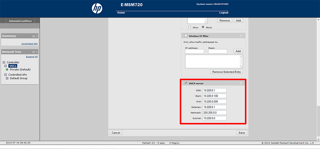
11. If using the controller for DHCP > Enable the DHCP Server and specify;
- DNS 10.220.0.1
- Start 10.220.0.100
- End 10.220.0.200
- Gateway 10.220.0.1
- Net mask 255.255.0.0
- Subnet 10.220.0.0
Create a Network Profile for Each of the New VSC’s
1. Home > Network > Network Profiles > Add New Profile.
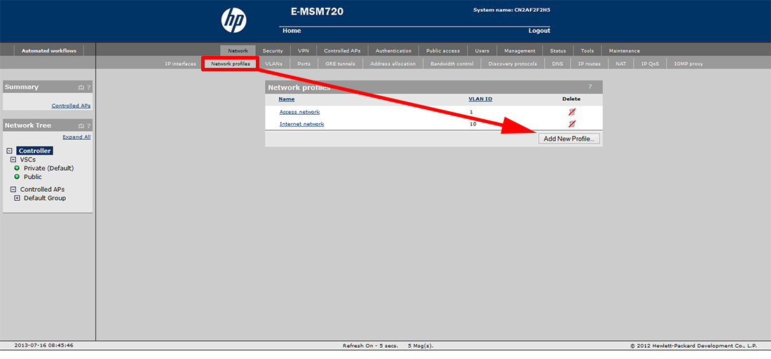
2. Call it ‘Private’ Tick VLAN ID select 1 > Save.

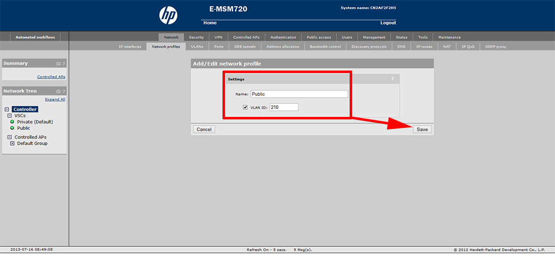
3. Add New Profile > Call it ‘Public’ > Tick VLAN ID and set it to 210 > Save.
4. At this point, connect your wireless AP’s to the network, and the controller should detect them.
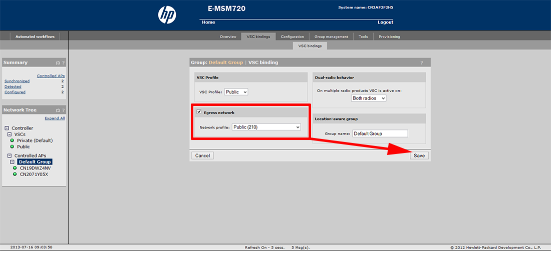
Bind the VSC’s to the Default AP Group (Using the network profiles we just created)
1. On the left hand menu > Controller > Controlled Alps > Default Group > VSC Bindings (top) > Select the ‘Private’ VSC Binding.
2. Make sure ‘Egress Network’ is NOT ticked and none is selected > Save.

3. Add New Binding > Select the ‘Public’ VSC Profile > Tick EGRESS NETWORK > Set the Network profile to ‘Public (210)’ > Save.
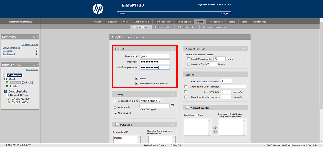
Create user accounts (Only if using HTML Based Authentication)
1. Home > Users > User Accounts > Add New Account > specify a name i.e guest > specify and confirm a password i.e. Password123.
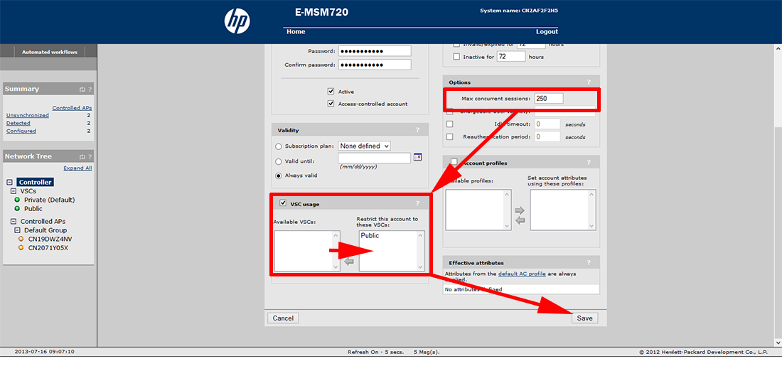
2. Change the MAX concurrent Sessions to 250 > Enable VSC Usage > Add the ‘Public’ VSC (right arrow) > Save.
Synchronize the Access Points to the MSM Controller
1. Home > Controller (left) > Controller APs > Overview Tab > Change the Action drop down to Synchronize Configuration > Apply.
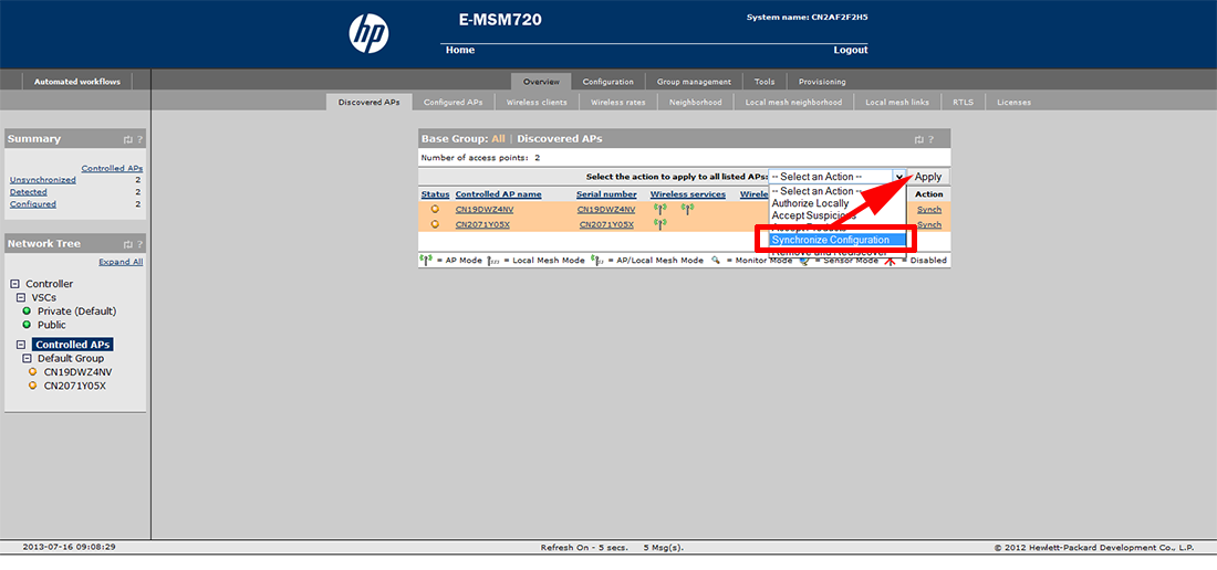
2. Wait for the APs to synchronize > Test both the SSIDs.
Related Articles, References, Credits, or External Links
NA