
KB ID 0001313
Problem
It’s a common problem, you want to connect one site to another and still have them on the same layer 2 network.
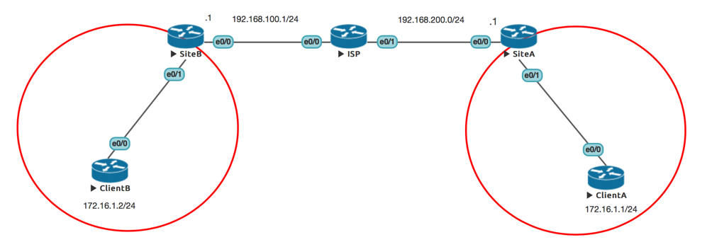
As you can see above both the routers at the bottom are in the 172.16.1.0/24 network, let’s assume they are clients in the same layer 2 network how would you connect them?
Solution
Option 1: xconnect over L2TP
All the ‘heavy lifting’ is done on the SiteA and SiteB routers. We will start with Site A. You create a pseudowire class, and specify the interface that will do the encrypting .
!
pseudowire-class CL-XCONNECT
 encapsulation l2tpv3
 protocol none
 ip local interface Ethernet 0/0
!
Set the public (internet facing) IP.
!
interface Ethernet0/0
 ip address 192.168.200.1 255.255.255.0
 no shut
!
Finally setup the private, (LAN facing) interface, and specify the ‘other side’ of the encryption tunnel, (the internet facing interface at SiteB.) Then setup a unique ID.
!
interface Ethernet0/1
 description LAN
 no ip address
 xconnect 192.168.100.1 1 encapsulation l2tpv3 manual pw-class CL-XCONNECT
 l2tp id 1 2
!
Site B is the mirror opposite;
!
pseudowire-class CL-XCONNECT
 encapsulation l2tpv3
 protocol none
 ip local interface Ethernet 0/0
!
interface Ethernet0/0
 ip address 192.168.100.1 255.255.255.0
!
interface Ethernet0/1
 description LAN
 no ip address
 xconnect 192.168.200.1 1 encapsulation l2tpv3 manual pw-class CL-XCONNECT
 l2tp id 2 1
!
To test you can use the ‘show l2tun tunnel all‘ command
Option 2: MPLS
Hang about! Isn’t MPLS very complicated? Well not for layer two networks. There are certain steps we have to take;
Backbone Routers (That will be Site A, SiteB, AND the ISP one.) We will need a loopback address, (don’t forget these addresses will need advertising into whatever routing protocol is running over the backbone).
Site A

!
interface Loopback1
 ip address 192.168.255.4 255.255.255.255
!

Site B

!
interface Loopback1
 ip address 192.168.255.3 255.255.255.255
!

ISP

!
interface Loopback1
 ip address 192.168.255.2 255.255.255.255
!
Backbone Routers: Enable MPLS on all the interfaces that will pass traffic;
Site A

!
interface Ethernet0/0
 ip address 192.168.200.1 255.255.255.0
 mpls ip
!

Site B

!
interface Ethernet0/0
 ip address 192.168.100.1 255.255.255.0
 mpls ip
!

ISP

!
interface Ethernet0/0
 ip address 192.168.100.254 255.255.255.0
 mpls ip
!
interface Ethernet0/1
 ip address 192.168.200.254 255.255.255.0
 mpls ip
!
Client facing interfaces:, (these can also be sub interfaces, if you are trunking). Need xconnect setting up, the syntax is as follows;
xconnect {ip of target loopback) {id-must-match-other-end} encapsulation mpls
Site A

!
interface Ethernet0/1
 description LAN
 no ip address
 xconnect 192.168.255.3 3000 encapsulation mpls
!


Site B

!
interface Ethernet0/1
 description LAN
 no ip address
 xconnect 192.168.255.4 3000 encapsulation mpls
!
Option 3: VPLS
Virtual Private LAN Service, is pretty much designed to do exactly what we want, it let’s us stretch layer two networks to multiple points, let’s assume both my network segments (above) need to be in VLAN 300, so they share the same broadcast domain.
The setup process is similar to MPLS, you create a loopback interface on the backbone routers, advertise those addresses into the routing protocol of your choice, then you enable ‘mpls ip‘. But then, on the routers that face the clients you need to create a ‘vfi‘ (virtual forwarding instance,) then attach that VFI to the VLAN interface that the clients are connected to.
!
l2 vfi VPLS-300 manual
 vpn id 300
 neighbor 192.168.255.3 encapsulation mpls
!
interface Vlan300
 mtu 1600
 xconnect vfi VPLS-300
!
Note: Obviously the physical interface connected to the clients, needs to be in VLAN 300, and don’t forget (at both ends), to make sure that vlan 300 is up (no shut).
To Test:
SiteA#show mpls l2transport vc 300

Local intf     Local circuit              Dest address    VC ID      Status
-------------  -------------------------- --------------- ---------- ----------
VFI VPLS-300   VFI                        192.168.255.3     300        UP

and

SiteA#show mac address-table vlan 300

Legend: * - primary entry
        age - seconds since last seen
        n/a - not available
        S - secure entry
        R - router's gateway mac address entry
        D - Duplicate mac address entry

Displaying entries from active supervisor:

     vlan   mac address    type   learn    age                 ports
----+----+---------------+-------+-----+----------+-----------------------------
*     300 0050.56ab.2eae  dynamic  Yes       90     VPLS peer 192.168.255.3(2:1)
*     300 0050.56ab.12ee  dynamic  Yes      340     VPLS peer 192.168.255.3(2:1)
In the bottom example, you can see MAC addresses being learned form the ‘other’ sire of the VPLS link.
Related Articles, References, Credits, or External Links
NA
24/05/2017
Hi Pete,
Good work.
Could you also elaborate which router should be taken into consideration while implementing the above in the GNS or any other practical simulators.
Cheers,
24/05/2017
Hi,
That image was taken from UNL – It’s the simulator I use now 🙂 And the one I used for testing the Lab.
Regards,
Pete
09/02/2021
Do you know what version of CAT6K IOS supports this, also what features or IOS for Nexus93180?
10/02/2021
Unsure – but I’ll throw it open for comment..