
KB ID 0001205
Problem
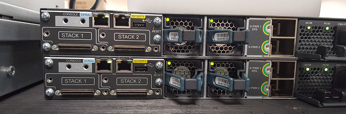
You can stack Cisco 3750-X Switches in groups of up to 9 switches, and they can then be managed as one switch. Here I’ve got 2 switches.
Solution
Removing 3750-X Switches Stack Configuration
One of my switches had already been in a stack, so I needed to remove its stack configuration. It thought it was switch 4 in the stack so I issued the following commands;
Switch(config)# no switch 4 provision
Switch(config)# wr mem
Cisco 3750-X Configure Stacking
Don’t connect any stacking cables yet, decide which switch is going to the the ‘master’ and log onto that switch, and issue the following commands;
Switch#configure terminal
Enter configuration commands, one per line.  End with CNTL/Z.
Switch(config)#switch 1 priority 15
Changing the Switch Priority of Switch Number 1 to 15
Do you want to continue?[confirm] {Enter}
New Priority has been set successfully
Switch(config)#do write mem
Building configuration...
[OK]

Switch(config)#do reload
Proceed with reload? [confirm] {Enter}
When the switch reloads you will see.
Waiting for Stack Master Election...
SM: Waiting for other switches in stack to boot...
###############################################################
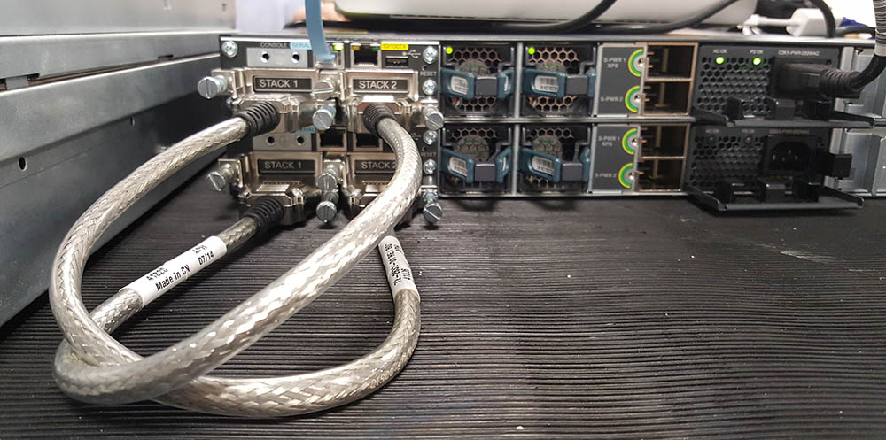
At this point you can connect the stack cables and power on the second switch. With multiple switches connect each stack port one, to the switch below’s stack port two. Then on the last switch connect its stack port one back to stack port two on the top switch, (so there is a ‘ring’.)
If you have more than two switches you can set their priority (as you did above) priority 15 will always win the ‘elections’ and be the master switch, number the rest accordingly. The default is ‘1’ so if you don’t then it works out the order based on MAC addresses, (which is not good!).
When all the switches are booted, check all is well;
Switch#show switch
Switch/Stack Mac Address : 74a2.e69a.0c00
                                           H/W   Current
Switch#  Role   Mac Address     Priority Version  State
----------------------------------------------------------
*1       Master 74a2.e69a.0c00     15     3       Ready
 2       Member 204c.9e5f.4000     1      3       Ready

Switch#show ip int brief
Interface              IP-Address      OK? Method Status                Protocol
Vlan1                  unassigned      YES NVRAM  administratively down down
FastEthernet0          unassigned      YES NVRAM  administratively down down
GigabitEthernet1/0/1   unassigned      YES unset  down                  down
GigabitEthernet1/0/2   unassigned      YES unset  down                  down
GigabitEthernet1/0/3   unassigned      YES unset  down                  down
GigabitEthernet1/0/4   unassigned      YES unset  down                  down
{----------------Output Removed For the Sake of Brevity---------------------}
GigabitEthernet1/1/1   unassigned      YES unset  down                  down
GigabitEthernet1/1/2   unassigned      YES unset  down                  down
GigabitEthernet1/1/3   unassigned      YES unset  down                  down
GigabitEthernet1/1/4   unassigned      YES unset  down                  down
Te1/1/1                unassigned      YES unset  down                  down
Te1/1/2                unassigned      YES unset  down                  down
GigabitEthernet2/0/1   unassigned      YES unset  down                  down
GigabitEthernet2/0/2   unassigned      YES unset  down                  down
GigabitEthernet2/0/3   unassigned      YES unset  down                  down
{----------------Output Removed For the Sake of Brevity---------------------}
GigabitEthernet2/1/1   unassigned      YES unset  down                  down
GigabitEthernet2/1/2   unassigned      YES unset  down                  down
GigabitEthernet2/1/3   unassigned      YES unset  down                  down
GigabitEthernet2/1/4   unassigned      YES unset  down                  down
Te2/1/1                unassigned      YES unset  down                  down
Te2/1/2                unassigned      YES unset  down                  down
Switch#
Make sure your stack cabling is OK;
Switch# show switch stack-ports summary

Switch#/  Stack   Neighbor   Cable    Link   Link   Sync      #         In
 Port#     Port              Length    OK   Active   OK    Changes   Loopback
          Status                                          To LinkOK
--------  ------  --------  --------  ----  ------  ----  ---------  --------
  1/1     OK         2      50 cm     Yes    Yes    Yes        1        No
  1/2     OK         2      50 cm     Yes    Yes    Yes        1        No
  2/1     OK         1      50 cm     Yes    Yes    Yes        1        No
  2/2     OK         1      50 cm     Yes    Yes    Yes        1        No

Switch# show switch stack-ring speed

Stack Ring Speed        : 32G
Stack Ring Configuration: Full
Stack Ring Protocol     : StackWisePlus
Switch#
If you are also using XPS redundant power cables remember that’s only supported for up to four switches, (without an extra XPS-2200 rack power unit). I power off the switches before I fit these.
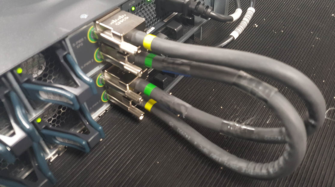
Why do they have green and yellow ends: If you look on the switch you will see the ‘socket’ is marked with a yellow and a green ‘semi-circle’. that means a green end or a yellow end can be plugged into that socket.
That makes no sense, so anything can plug into anything, why colour code them? That’s because there is a different cable that has a ‘red’ end on it for plugging into an XPS-2200 rack power supply, like this;

Then to test your XPS Power Cables.
Switch>show env power all
SW  PID                 Serial#     Status           Sys Pwr  PoE Pwr  Watts
---  ------------------  ----------  ---------------  -------  -------  -----
1A  C3KX-PWR-350WAC     LIT18410MD4 OK              Good     Good     350/0
1B  Not Present
2A  C3KX-PWR-350WAC     LIT18410JJ3 OK              Good     Good     350/0
2B  Not Present

Switch#show stack-power neighbors
Power Stack           Stack   Stack    Total   Rsvd    Alloc   Unused  Num  Num
Name                  Mode    Topolgy  Pwr(W)  Pwr(W)  Pwr(W)  Pwr(W)  SW   PS
--------------------  ------  -------  ------  ------  ------  ------  ---  ---
Powerstack-2          SP-PSS  Ring     700     320     380     0       2    2

    Power Stack           Port 1  Port 1             Port 2  Port 2
SW  Name                  Status  Neighbor SW:MAC    Status  Neighbor SW:MAC
--  --------------------  ------  ----------------   ------  ----------------
1   Powerstack-2          Conn    2:204c.9e5f.4000   Conn    2:204c.9e5f.4000
2   Powerstack-2          Conn    1:74a2.e69a.0c00   Conn    1:74a2.e69a.0c00
Stack Power Profiles (Setting Up)
Stack Power Modes
Default (Power sharing Mode): All the power from all the power supplies, is aggregated together, and no power is reserved – if a power supply failed there is a chance that there might not be enough power.
Redundant Mode: The power supplied by the largest power supply in the stack, is taken away from the total power output in case there is an outage.
Stand Alone Mode: Stops a switch participating in a power stack completely.
Each mode can be configured to run strict, or non-strict, (with the exception of a stand alone mode).
Strict: If actual power drops below budgeted power, things may get powered down.
Non Strict: Actual power can run above budgeted power, if that extra power is available.
Switch(config)# stack-power switch 1 port 1 enable
Switch(config)# stack-power switch 1 port 2 enable
Switch(config)# stack-power switch 2 port 1 enable
Switch(config)# stack-power switch 2 port 2 enable
Switch(config)# stack-power stack Power-Stack-1
Switch(config-stackpower)# mode redundant
Switch(config-stackpower)# stack-power switch 1
Switch(config-stackpower)# stack-power switch 2
Switch(config-stackpower)# exit
Related Articles, References, Credits, or External Links
Cisco Catalyst – Upgrading ‘Stacked’ Switches
26/06/2016
Hi Pete,
Great article. One thing I would add is to also create a stackpower profile to explicitly define either redundant or power sharing.
27/06/2016
Updated 🙂
11/04/2018
Great Information for stacking cisco 🙂 thank you.
24/07/2020
Nice great info all in one place.
Thanks for sharing
03/06/2022
Awesome. This is a very good explanation. Thank you